
A recent article in BBC Science Focus had the following statement from Dr. Kirsty King: “Lie detectors don’t work. Body language is unreliable. But there are ways to tell if someone is lying. You just have to listen carefully to what they’re saying. Spotting a liar is a vital skill. We all want to be better at it because lies can affect us in any number of ways, some of them harmful.”
You know what one-line diagrams are. They tell you how a system was designed, and it gives you the road map to the electrical infrastructure. It helps you plan switching and maintenance tasks. But it doesn’t tell you everything that can energize the equipment you’ll be working on today.
When it comes to electrical safety, don’t let a one-line be a liar—identify and spot those hidden gotchas before they get ‘cha.
PICTURE THIS
You are part of a crew that arrives to test a low-voltage switchgear lineup during a planned maintenance outage. The customer has opened the upstream breaker. The main disconnect is locked and tagged. The mimic bus shows the section de-energized, and the one-line shows no second source of power. Everyone agrees that the equipment is dead.
Then a technician puts a meter on a control terminal and finds 120 volts present. (Side note: Great job, Super Tech! You just did test-before-touch in accordance with NFPA 70E Article 120.6(7).)
That changes everything—but it may also have prevented an injury. So where did that voltage, that wasn’t identified on the one-line, come from? Was it a separate control power transformer, a battery system, a temporary feed, or simply a modification that never made it on the drawing? The important thing is this: the system didn’t match the picture of what should have been there. The one-line lied to you.
You’ve all probably seen a similar situation before. (I have!) Every experienced test technician has seen some version of it. A circuit breaker says open, but it’s closed. A tie breaker was closed that should have been open. A control circuit came from another lineup. A customer-installed jumper appeared in the switchgear without documentation. A supposedly discharged capacitor still held energy. It goes on and on…
That’s why understanding and following NFPA 70E is so important. We should all be very familiar with Article 120.6, Process for Establishing and Verifying an Electrically Safe Work Condition. It gives us a specific procedure for establishing and verifying an electrically safe work condition. And these steps (there are nine of them) within the 70E matter because no single indication proves that equipment is safe.
A drawing, an open breaker, a tag and a lock, and an operator’s verbal statement all provide useful information, but none of them can take the place of you verifying the absence of voltage at that critical point of exposure—the place you are about to touch. (So test it, Electro-Boy!)
YOUR STARTING POINT: THE ONE-LINE DIAGRAM
OK, we’re giving the one-line a lot of grief by calling it a liar, but truth be told, a one-line diagram is one of the most useful documents on a job, and its importance to overall safety and maintenance planning is critical. It shows the intended sources, buses, transformers, protective devices, and normal connections.
It helps us plan isolation points and understand how equipment should operate.
Did you catch that? It tells us that the equipment should operate. That’s a big ask, but also remember this: a one-line often describes the system as designed or as last documented. It may not show a temporary generator, portable cables, an added UPS, an external control-power source, or a field modification made during an emergency. Depending on the customer or the facility, you might get lucky, and the drawings may remain accurate for years… but real-world field conditions often reveal that’s just simply not the case.
That doesn’t make the drawing useless; it means the drawing is one piece of evidence in the quest to isolate and verify sources of energy. The technician must compare it with equipment nameplates, conductor routing, device positions, local and remote indications, operating records, and actual electrical measurements.
Think about it like this: your safest mindset is to treat the drawing as a theory of the system. Your job is to test that theory before your body enters the circuit. They might not lie to you as much as politicians do, but sometimes the drawings might tell you the truth, just not always the whole truth. (Vote for me!)
OPEN DOES NOT MEAN DE-ENERGIZED!
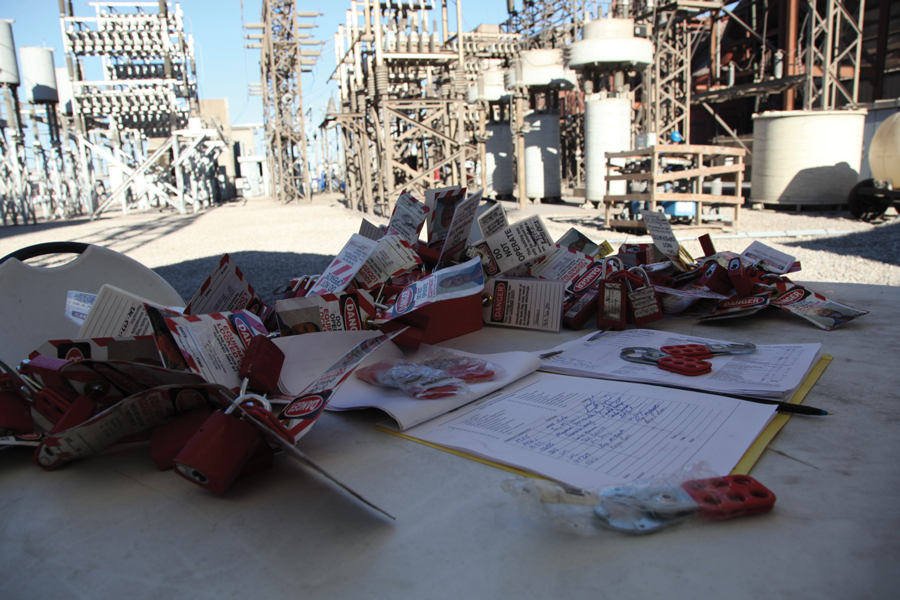
An open breaker tells you something about the position of a device. It does not prove that you opened the right device, that every pole is separated and isolated from the source, or that another source cannot reach the work area. It also does not prove that stored or induced energy is gone.
OSHA makes this point directly in 29 CFR 1910.333(b)(2)(iv)(B), which states in part:
A qualified person shall use test equipment to test the circuit elements and electrical parts of equipment to which employees will be exposed and shall verify that the circuit elements and equipment parts are deenergized. The test shall also determine if any energized condition exists as a result of inadvertently induced voltage or unrelated voltage backfeed even though specific parts of the circuit have been deenergized and presumed to be safe.
That final phrase deserves attention because it describes the voltage nobody expected to find.
NFPA 70E Section 120.6 addresses the process for establishing and verifying an electrically safe work condition. Identification, interruption, isolation, lockout or tagout, release of stored energy, absence-of-voltage testing, and temporary protective grounding where required work together. Removing any one of these steps weakens the overall intent and result.
The point is not that breakers, locks, tags, and drawings cannot be trusted. The point is that each control answers a different question. The absence-of-voltage test answers the final question: What is the electrical condition at the place where the employee (that’s you!) may be exposed?
LOOK FOR ENERGY SOURCES HIDING IN PLAIN SIGHT
Unexpected energy is often ordinary energy entering by an overlooked path.
Read that again.
“Unexpected energy is often ordinary energy entering by an overlooked path.”
When on a maintenance outage, here’s a few examples of energy sources that deserve your attention during planning and execution of tasks:
- Separate control power. Trip, close, relay, metering, space-heater, and auxiliary circuits may remain energized after the primary source is isolated.
- Generators and transfer switch equipment. Automatic starting controls, closed transition switches, and alternate sources of supply can change the assumed state of a bus.
- UPS and battery systems. AC input isolation does not remove DC energy or output supplied by an inverter!
- Photovoltaic and battery energy storage. Multiple conversion stages of energy and various sources can energize equipment from directions that older one-lines did not anticipate.
- Capacitors and VFD DC buses. Stored electrical charge on capacitors can remain after energy isolation.
- Voltage and control power transformers. A secondary source can create an unexpected backfeed path through a transformer.
- Induction. Nearby energized conductors can produce measurable and hazardous voltage on isolated conductors, especially over long parallel runs or in high-voltage substations.
- Temporary wiring and undocumented changes
- Watch this one—it will get you. Outage work, construction, heating up the coffee pot, or emergency repairs often introduce energy sources that do not appear on the drawings.
YOUR TEST SETS CHANGE THE SYSTEM
Test technicians face a condition that many electrical safety discussions barely address: we bring energy to the job.
A circuit may begin in an electrically safe work condition. But once the test leads are connected and the test set is energized, that condition changes. Insulation-resistance testing, high-potential testing, primary- and secondary-injection testing, turns-ratio testing, breaker timing, and functional testing can introduce voltage, current, stored charge, or mechanical movement. (Remember, energy is both electrical and mechanical!)
The test source may also reach farther than expected. A lifted lead may still connect to another device. A CT circuit can develop hazardous voltage if opened under the wrong conditions. A test voltage can appear at the far end of a cable. A breaker can operate remotely while another worker has their hands inside the mechanism. A motor or generator can jog or rotate.
This leads to a rule that belongs in every maintenance test plan and job hazard analysis (JHA)—account for not only the facility’s energy, but the possible energy sources introduced by the test crew. If you take time to perform a short safety briefing, it can prevent a long post-accident investigation.
OK, so now you have the ANSI/NETA specs out, you are about to test the device. Ask yourself these seven questions:
- What normally supplies this equipment?
- What could supply it under an abnormal or temporary condition?
- What energy will our test equipment introduce?
- Where can that energy travel, including through control wiring, transformers, grounds, and connected equipment?
- Who controls each source and who can change its state?
- What must be isolated, discharged, restrained, blocked, or grounded?
- How will we verify the condition at every point where a person may be exposed?
TRUST THE PROCESS AND VERIFY THE SYSTEM
Verification is how you, as an experienced test technician in the field, close the gap between your field-testing execution plan and the actual electrical system.
Plant personnel may have followed the switching order exactly. The electrician may have applied every lock correctly. The engineer may have issued the best drawing available. But if there is a failed contact, a hidden source of power, a wiring error, or an undocumented change, you can still have unexpected energy at the work location. The meter does not assign blame; it reports the condition.
Your experience teaches us what normally happens, but electrical safety processes ask us to consider what else can happen. You know: “Trust, but verify.”

It takes me back to an article I wrote for NETA World in Summer 2023 about the possible effects of AI on future electrical standards—and the infamous quote by U.S. President Ronald Reagan, which came about from Suzanne Massie, an American scholar of Russian history.
She advised Reagan on the Soviet Union during the final years of the Cold War, and as they prepared for talks with Mikhail Gorbachev, she taught him the Russian proverb, “Doveryai no Proveryai,” which translates to “Trust, but Verify.”
The next time the breaker is open, the lock is on, and you look at the drawing that says the bus is dead, look around and ask yourself one more question before you reach in: What could still put energy here?
Then test the answer. Don’t let it lie to you.
And remember this: test before touch!
REFERENCES
- BBC Science Focus. “How to Catch a Liar Using Language.” BBC Science Focus. www.sciencefocus.com/wellbeing/how-to-catch-a-liar-language
- NFPA 70E, Standard for Electrical Safety in the Workplace. 2027 ed. www.nfpa.org/product/nfpa-70e-standard-for-electrical-safety-in-the-workplace/p0070ecode
- Occupational Safety and Health Administration. “29 CFR § 1910.333: Selection and Use of Work Practices.” Occupational Safety and Health Standards. U.S. Department of Labor. www.osha.gov/laws-regs/regulations/standardnumber/1910/1910.333

Ron Widup has worked in the electrical power testing and maintenance industry for more than 45 years. He serves as Chief Technical Marketing Officer for Vector Power in Plano, Texas. Ron has been an active member of several NFPA technical committees, including NFPA 70E, NFPA 70B, NFPA 790/791, and NEC CMP-11. He serves on the InterNational Electrical Testing Association (NETA) Board of Directors and the NETA Standards Review Council. He is also Chairman of IEEE P902, IEEE Recommended Practice for Maintenance and Operational Safety of Electrical Power Distribution Systems in Industrial and Commercial Facilities. Ron currently serves as Chairman of the Texas State Technical College (TSTC) System Board of Regents. His credentials include NETA Certified Level 4 Senior Test Technician, State of Texas Journeyman Electrician, NFPA Certified Electrical Safety Compliance Professional (CESCP), and Senior Member of IEEE.