

Large generators, such as coal-fired and nuclear, are grounded through a high impedance to limit fault current flowing in the stator winding during ground faults. The high impedance is a resistor located across the secondary winding of a single-phase distribution transformer connected from the machine neutral to ground.
Large generators typically have a main set for protection and a backup set. The protection is typically a multi-function generator protection relay. The main and backup protection may or may not be identical. The trip logic typically used is referred to as one-out-of-two (1oo2); if either the main or backup protection operates, then a trip is issued. If either relay fails, then the scheme inherently reverts to one-out-of-one (1oo1) logic.
TWO-OUT-OF-THREE (2OO3) TRIP LOGIC
Nuclear generators are an exception since they are few and far between, while providing the most power output. As such, nuclear generators tend to have special protection requirements, such as trip logic. This article demonstrates how to apply 2oo3 logic using relay-to-relay communications to assert specific trip outputs. This eliminates the need for much wiring.
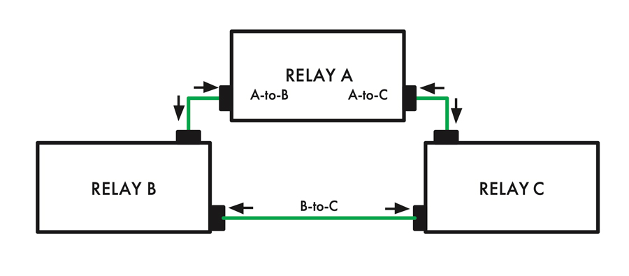
The 2oo3 trip logic requires that at least two out of the three main generator protection relays operate for a specific condition, such as an internal stator ground fault (e.g., 64G1). Figure 1 illustrates the relay communications. Each relay must communicate with the other two and vice versa, and each communication link is bi-way. Therefore, each relay continuously knows the status of the other two relays’ tripping elements via the communication links.
Two out of the three relays must operate via a particular protection element in order for a trip to be issued, such as 64G1 neutral overvoltage. Figure 2A illustrates this logic.
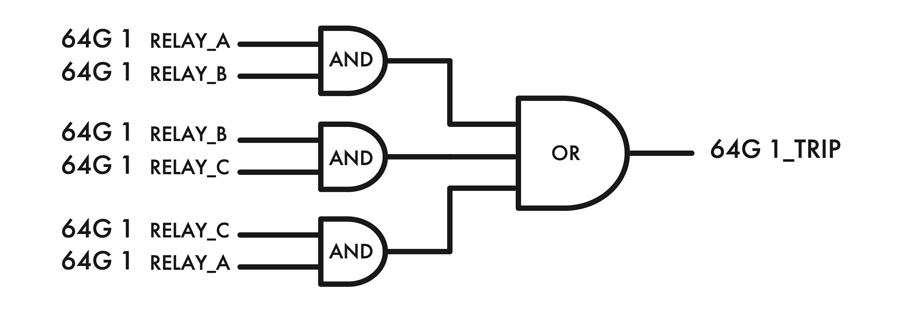
Each relay has 2oo3 logic programmed for each specific trip condition (e.g., loss-of-field). The trip contacts for each specific trip from the three relays are wired out in parallel, as illustrated by Figure 2B. Using relay-to-relay communication greatly reduces the amount of wiring required.

ADAPTIVE SCHEME LOGIC
Ideally, each relay should have independent VTs, CTs, and DC batteries; however the vast majority of nuclear power plants were built decades ago. It is rare to ever have three independent sets of batteries. Therefore, two of the three relays must likely be sourced by one battery. The trip logic must automatically adapt if this common battery fails, or else tripping is not possible.
Suppose, for example, that relays B and C are both sourced by the same battery. Figure 3 illustrates how to switch over to a one-out-of-one (1oo1) scheme, relying solely upon relay A until the situation with the defective battery can be remedied.
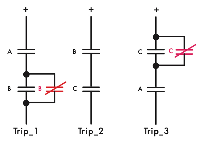
Normally closed output contacts for relays B and C are connected in parallel with the respective normally open trip output contact. Relay A can independently trip via paths Trip_1 and Trip_3 should the battery sourcing relays B and C ever fail. Each normally closed output contact falls closed when the relay power supply is dead.
ONE-OUT-OF-TWO TAKEN TWICE (1OO2X2) TRIP LOGIC
Another popular trip scheme used is one-out-of-two taken twice, which is simply two one-out-of-two trip schemes connected in series, as illustrated in Figure 4. This scheme is biased towards dependability. This scheme can also be realized using relay-to-relay communication.
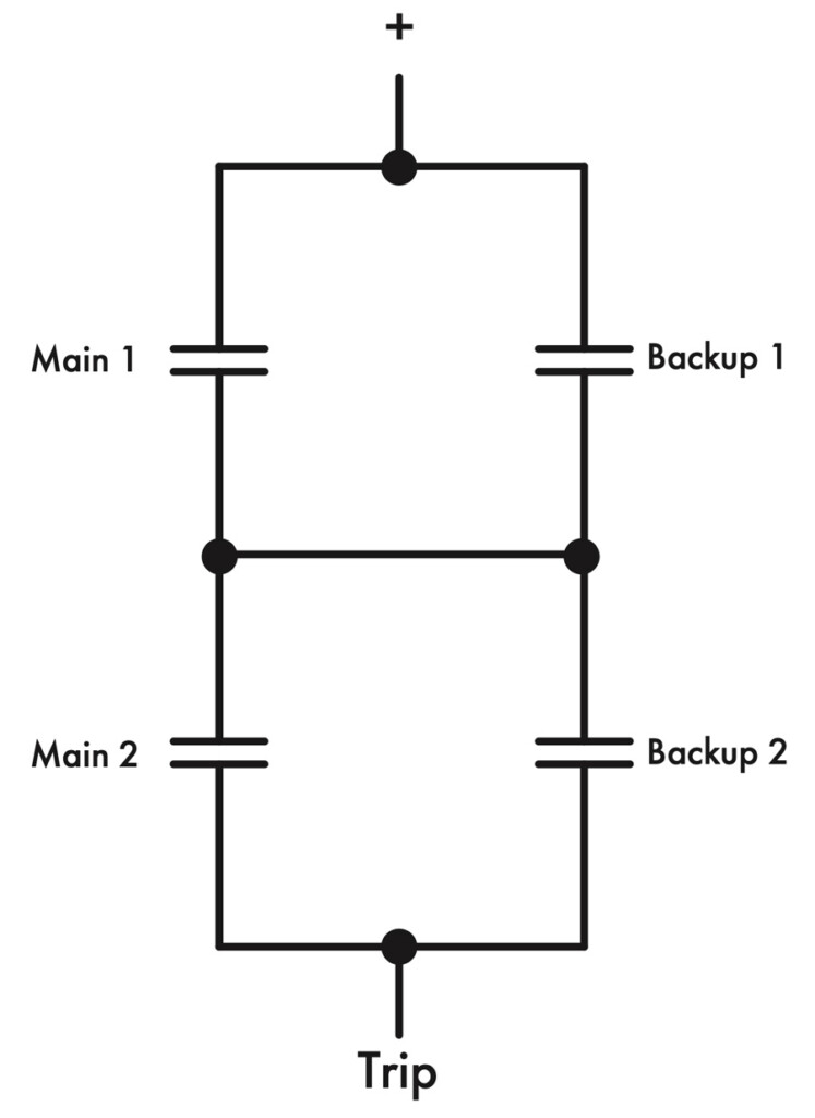
Figure 5 illustrates how this trip scheme can be modified so it is adaptive.
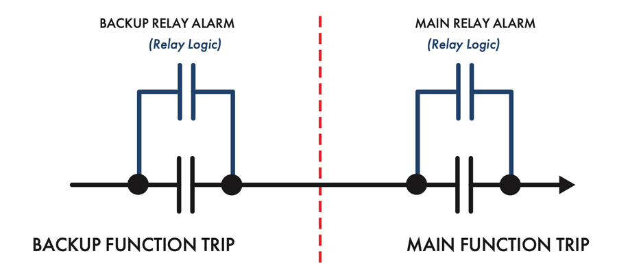
The relay alarm output can be realized using programmable relay logic, so extra output contacts are not required, for example:
OUT202 := (40Z1T OR 40Z2T) OR (HALARM OR SALARM)
CONCLUSION
This article shows how to realize two trip logic schemes that require three or more relays. One scheme is biased toward security, while the other is biased more toward reliability. Using relay-to-relay communication greatly reduces the amount of wiring required.

Steve Turner is a Consultant at Sargent & Lundy. He was previously in charge of system protection for the Fossil Generation Department at Arizona Public Service Company for five years. Turner formerly held positions at Beckwith Electric Company, GEC Alstom, SEL, and Duke Energy, where he developed the first patent for double-ended fault location on overhead high-voltage transmission lines and was in charge of maintenance standards in the transmission department for protective relaying. He has BSEE and MSEE degrees from Virginia Tech University. Turner is an IEEE Senior Member and a member of the IEEE PSRC and has presented at numerous conferences.