
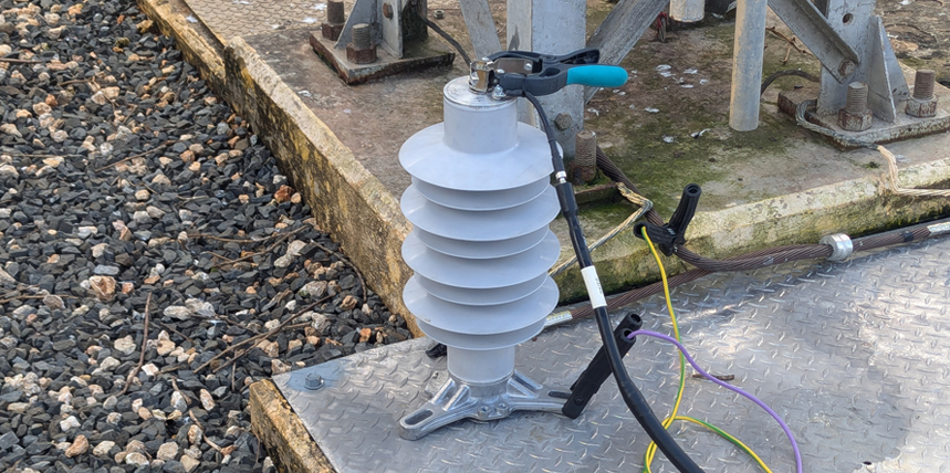
If you’ve done power factor testing, you will have noticed that while said testing yields multiple valuable parameters—e.g., watts loss, capacitance, total current, etc.—power factor itself gets the most attention. Indeed, power factor is a critical indicator of electrical equipment performance. However, an important exception to this claim exists, and it exists for surge arresters.
Power factor is the ratio of resistive current IR to total current IT, or IR /IT. Total current is a Pythagorean sum of resistive current IR and capacitive current IC, where IT = √(IR2 + IC2). Perfect insulation is insulation that permits zero resistive current. In that context, IC would equal IT. However, all insulators admit some resistive current, so traditional estimates of equipment condition focus on how far the asset’s power factor is from zero. Thus, 0.3% power factor is better than 0.4% power factor, which in turn is better than 0.5% power factor, and so on.
The trouble with using this parameter as a metric for surge arrester condition is that surge arrester capacitance is usually very low. Capacitance C is a function of frequency f and capacitive reactance XC, where C = 1/(2πfXC). This means that as capacitance decreases at any given test frequency, capacitive reactance rises. As capacitive reactance rises, given any test voltage VT, capacitive current IC falls, or VT/ XC = IC. If capacitive current falls and resistive current is constant, total current falls. If total current falls due to lower capacitive current, power factor rises.
But while rising power factor is associated with equipment degradation, it is traditionally considered problematic when said power factor increase is caused by rising resistive current, not falling capacitive current. The job of insulation is to block resistive current; therefore, comparisons of surge arresters based on power factor results influenced by low capacitive currents will be erroneous.
FIELD SCENARIO
Consider the results for three 36-kV surge arresters tested two years ago (Table 1).
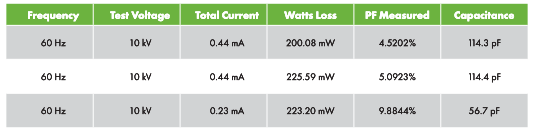
The top two arresters, #1 and #2 were brand-new, while #3 was service-aged. The decision was made to discard arrester #3 because its power factor was higher than those of #1 and #2. In retrospect, this might have been a mistake because of power factor unreliability for arresters.
First, notice that the calculated watts loss of arrester #3 is between that of #1 and #2. If arrester #3 was more degraded than its counterparts, we’d expect its watts loss to exceed those of #1 and #2.
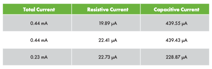
Moreover, consider the effect of capacitance (Table 2). The capacitance of arrester #3 at 56.7 pF is less than half the capacitances of #1 and #2. As a result, while the capacitive current of #3 is around 228.87 µA, the capacitive currents of #1 and #2 are approximately 439.55 µA and 439.43 µA, respectively. This at least partially accounts for why #3’s power factor is so much higher than the power factors of #1 and #2, accounting for test-set measurement error. Meanwhile, the other constituent of power factor, resistive current, is fairly similar across all three arresters.
SUMMARY
The caution against relying on power factor results goes beyond surge arresters. IEEE Std. C57.152-2013, IEEE Guide for Diagnostic Field Testing of Fluid-Filled Power Transformers, Regulators, and Reactors, states:
PF calculations should not be used to determine the integrity of insulation if the measured current is less than 0.3 mA. At low measured currents, PF calculations are susceptible to large swings, which could be misleading. Therefore, in those cases, the test results should be evaluated based on current and loss readings.
Low-capacitance assets will be overrepresented among assets with total currents less than 0.3 mA. This means that many SF6 breakers would be subject to this proviso, since they also tend to have low pole-to-pole and pole-to-ground capacitance. This caution against using power factor on low-capacitance assets applies equally to dissipation factor, also known as tan delta calculations. Because tan delta = IR /IC, the same issue of low capacitance causing low capacitive current exists.
The more data you produce, the better. Single tests of arresters are of limited value. The more test results for a given arrester, the clearer the watts loss trend one can develop for the condition of said arrester.
REFERENCES
IEEE. IEEE Std. C57.152-2013, IEEE Guide for Diagnostic Field Testing of Fluid-Filled Power Transformers, Regulators, and Reactors.

Michael Labeit is a Prime Power Production Specialist, Lineman, a Power Systems Technician for ASRC Energy, and a NETA Level 3 Technician in the 249th Engineer Battalion, U.S. Army Corps of Engineers. He has operated and maintained medium-voltage power plants in Turkey and Saudi Arabia as well as at Ft. Leonard Wood, Missouri, and Ft. Bragg, North Carolina. Labeit graduated from Prime Power School in 2018 and has an AAS from Excelsior College.