
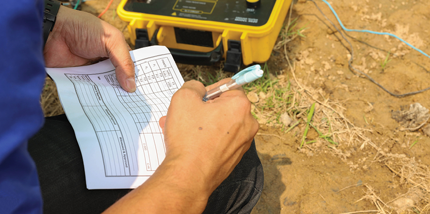
The gold standard for grounding testing is IEEE Std. 81–2025, Guide for Measuring Earth Resistivity, Ground Impedance, and Earth Surface Potentials of a Grounding System. Its purpose is to assist engineers and technicians in obtaining accurate, reliable grounding system measurements and interpreting data for design validation. This standard covers:
- Safety considerations
- Measuring earth resistivity, power system frequency resistance or impedance of the ground system, touch and step voltages, and transient/surge impedance
- Verifying the integrity of the grounding system
- Common test methods, instrumentation characteristics and limitations, and factors that can distort test measurements
In addition to being familiar with this standard, successful testers must also be aware of grounding test equipment options, their pros and cons, and the correct application of each device.
SAFETY FIRST
Many years ago, grounding testing relied on low-current, low-power test equipment, and sites could often be tested successfully using the fall-of-potential (FOP) method. Today’s equipment is much more powerful, and therefore more dangerous. One critical hazard includes induced voltages and current on the test leads due to capacitive and inductive coupling from overhead lines or underground power cables. Voltage can be sourced at a site other than the site under test or from other energized sources in the area, even if the site under test is de-energized.
A written job safety analysis (JSA) with a briefing must be conducted prior to testing. All team members should understand the testing process and potential safety hazards and have the authority to stop work to resolve issues. Test personnel should maintain clearance from the test probes when energized by test sets producing more than 50 V.
DEFINITIONS PER IEEE STD. 81
The new IEEE Std. 81, released in November 2025, covers four new and redefined ground testing terms:
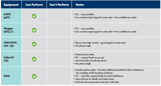
- The integrity test is a measure of electrical continuity between two or more conductive items that, when energized, will become an acceptable path for current conduction with a negligible voltage drop across the elements and their points of interconnection. The test equipment is specified as requiring either a large enough signal to make errors due to power system noise (and other sources) negligible by comparison, or using other means, such as filtering, signal type, and polarity, to adequately reject errors due to site noise.
- An impedance (or resistance) test is a measured value between a ground system and remote earth that can validate the performance of a new or existing grounding system. Some test equipment methods require the site to be isolated to measure impedance/resistance accurately.
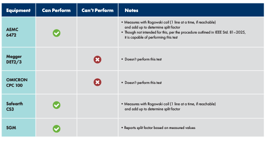
- A current distribution measurement is used to validate and determine current splits. The intent is to determine the contribution that each current path makes and calculate its apparent impedance. The test can identify paths that require further investigation and identify potential transfer hazards. This test is limited to evaluating only accessible grounding paths.
- The existing current injection test (CIT) term has a new definition. Per the new standard, this test is an injection of an AC test signal at a frequency different from the nominal power frequency to minimize interference into the grounding system over the following:
Overhead. A transmission feeder line, the preferred method, requires a transmission line outage, which is rarely feasible and adds considerable expense and complexity.
Overland. This test does not utilize an existing conductor and will require deployment of a test lead conductor.
The CIT measures ground potential rise (GPR), touch voltage, step voltage, mesh voltage, and transfer voltage for a response at key locations. It can measure the zone of influence for telecommunication equipment and provide an evaluation of the expected grounding system performance by scaling the measured response to the value expected during a ground fault.
Test Equipment
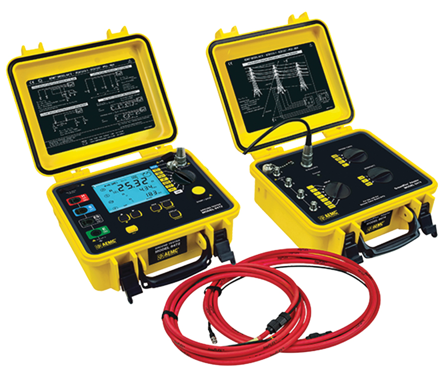
Image courtesy of AEMC® Instruments
AEMC 6472 + 6474 + ACCESSORIES*
Although AEMC and Megger have been around for a long time and offer newer versions of their test equipment, many pitfalls still exist in today’s grounding testing, specifically, limited current output that can’t overcome test lead interference (low signal-to-noise ratio). This equipment is:
- Less expensive ($16K)
- DC power, portable
- 250 mA output—very limiting in field testing, even on small sites
- Output frequency 0–440 Hz
- No user interface data—requires the user to interpret data points in the field to determine validity
- Available for rental
Test Equipment
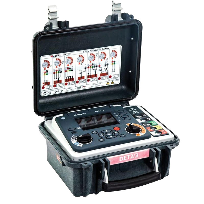
Image courtesy of Megger
MEGGER DET 2/3*
- Inexpensive ($6K)
- DC power, very portable
- 50 mA output—extremely limiting in field testing, even on small sites
- Output frequency 10–200 Hz
- No user interface data—requires the user to interpret data points in the field to determine validity
- Available for rental
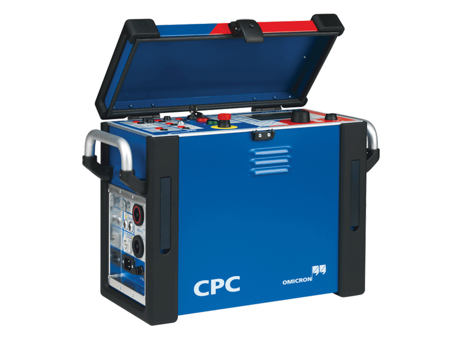
Test Equipment
Image courtesy of OMICRON
OMICRON CPC 100 (OR COMPANO 100)*
- Expensive ($70K+)
- Training recommended
- Requires AC power for CPC 100 and DC power for COMPANO 100
- Provides real-time data feedback during testing
- Data recorded on tablet/computer
- CPC 100 = 3 A output
COMPANO 100 = 200 mA output - CP CU1 = 100 A/50 V or 10 A/500 V output (overhead injection)
- CPC 100 = 3 A output
- Output frequency 15–400 Hz
- Available for rental

Test Equipment
Image courtesy of Safearth
SAFEARTH AX1 & CS3*
- Expensive ($80K+)
- Requires training
- Requires AC or DC battery power
- Data must be recorded by hand—no associated software for field testing (some software for post-test analysis)
- No user interface data—requires the user to interpret data points in the field to determine validity
- 32 A output (overhead)
- Output frequency 40–70 Hz
- Due to training requirements and complexity, not available for rental
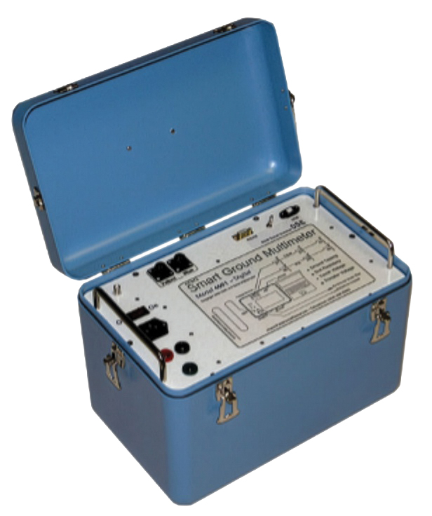
Test Equipment
Image courtesy of Advanced Power Concepts
SMART GROUND MULTIMETER (SGM)*
- Expensive ($75K+)
- Requires training
- Requires AC power
- Provides extensive real-time data feedbac during testing
- Connected computer records all data
- 16 A output (overland)
- Output frequency 0–250 Hz default.
User selectable to 2,000 Hz. - Due to training requirements and complexity, not available for rental
INTEGRITY
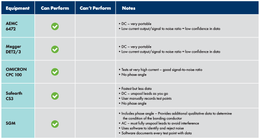
GROUND IMPEDANCE/RESISTANCE
CURRENT DISTRIBUTION/SPLIT FACTOR
CURRENT INJECTION

KEY TAKEAWAYS
The FOP test is still commonly specified, but unbeknownst to most owners, engineers, and testers, it is rarely successful. There is no validation of data nor error reports—all you get is a number. Grounding testing has become much more complicated and expensive than most people realize due to the new standard, test equipment requirements, and time on site. Test personnel must know the grounding test requirements (scope of work) and have extensive knowledge of IEEE Std. 81–2025, including test equipment applications and limitations. Manufacturer training is necessary, particularly with the higher-end test equipment (OMICRON, Safearth, SGM). Custom equipment training, preferably a combination of classroom and hands-on field testing, is the most inclusive option and essential to successful testing.
The less expensive test equipment, while tempting due to the lower cost, portability, and ease of use, is extremely constrained due to limitations in current output. Only very small, rural, de-energized, isolated sites are likely to be successful. The higher-end test equipment requires a substantial upfront investment in both cost and training and is best considered when many ground testing projects are anticipated, as the learning curve is steep.

Jacob Rioux is a Grounding Specialist at Hood Patterson & Dewar, Inc. With a background in substation design and testing, Rioux provides substation and facility grounding system testing and safety analysis. He also performs soil resistivity testing and grounding system design for new construction. His client base includes electric utilities and industrial and commercial facilities. He provides grounding articles, training, and presentations for conferences and clients nationwide. Rioux has a BS in mechanical engineering technology with a minor in electrical engineering technology from the University of Maine.

Lee Howard is a Senior Grounding Specialist with Hood Patterson & Dewar, Inc. With more than 25 years of experience, Howard specializes in the design and analysis of grounding, lightning protection, and surge suppression systems. He speaks at various industry conferences and offers grounding testing and consulting services to a wide range of domestic and international clients, including electrical utility, industrial, and commercial sites. Howard holds two patents in grounding and lightning protection products. He earned a BS in electronics engineering technology at DeVry University and a Power Systems Certificate from the Georgia Institute of Technology