
Fall-of-potential (FOP) testing is widely regarded as one of the most reliable methods for evaluating grounding system performance. Under ideal conditions, the procedure is straightforward: Electrodes are driven into the soil at prescribed intervals, measurements are recorded, and resistance values are calculated with a high degree of confidence.
In practice, however, technicians often encounter less-than-ideal environments. Urban and industrial sites often feature sprawling paved surfaces or concrete jungles that prevent the use of conventional driven electrodes. Arriving on-site to find a large parking lot or a fully developed facility footprint is a common scenario—one that presents immediate challenges to standard testing methodology.
Rather than abandoning testing efforts or resorting to destructive measures, such as jackhammering out chunks of the customer’s nicely paved roadway, technicians can employ alternative techniques that leverage the physical and electrical properties of these surfaces. With a clear understanding of grounding principles and material behavior, accurate and repeatable results can still be achieved.
This article reviews the fundamentals of FOP testing and presents practical field techniques for conducting tests in environments where traditional electrode placement is not feasible.
FALL-OF-POTENTIAL TESTING
FOP testing is used to determine the resistance of a grounding electrode system to earth, commonly expressed as Rg. This value represents the effective resistance between the grounding system and the surrounding soil mass, and it is a key parameter for assessing a system’s grounding provision, mat, or network performance and safety.
The test is performed by injecting a known current between the grounding electrode under test (depending on the test set used, these probes may be tied to the E, X, or C2 terminal of the equipment) and a remote auxiliary electrode, often referred to as the current or outer A third electrode (equipment terminal H, Z, or C1). A potential electrode (equipment terminal S, Y, or P), or “walking electrode,” is placed at evenly spaced, linear intervals along the line between the test and auxiliary electrodes. At each position, the voltage between the grounding electrode and the potential electrode is measured. By applying Ohm’s Law, the resistance can be calculated, as seen in Figure 1.
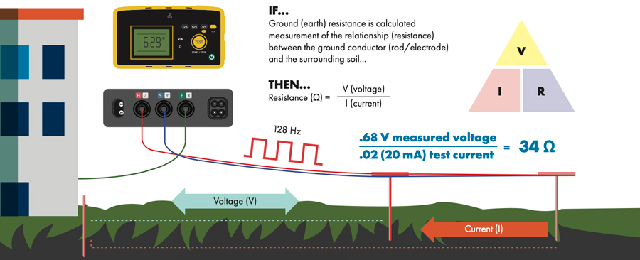
IMAGE COURTESY AEMC® INSTRUMENTS
As the potential electrode is moved farther from the grounding system, the measured voltage reflects the diminishing influence of the system’s hemispherical range of influence. Plotting these values typically produces a curve from which a stable resistance value can be identified.
The test setup generally consists of a ground test instrument connected to three electrodes. The grounding electrode is connected directly to the system under test, while the current and potential electrodes are usually metal stakes driven into the earth. In soils that are loosely compacted, moist, and moderately conductive, this process is efficient and reliable. These ideal conditions, however, are not always what a technician encounters on site.
GOING THE DISTANCE
Proper electrode spacing is essential for obtaining accurate fall-of-potential measurements. The distance between the grounding electrode and the current electrode must be sufficient to prevent their respective spheres of influence from overlapping.
A grounding system’s electrical influence extends outward in a hemispherical pattern (Figure 2), the size of which is determined by several factors, including soil resistivity, electrode geometry, burial depth, and the magnitude of injected current. Larger and deeper grounding systems require greater electrode spacing to fully capture this influence.
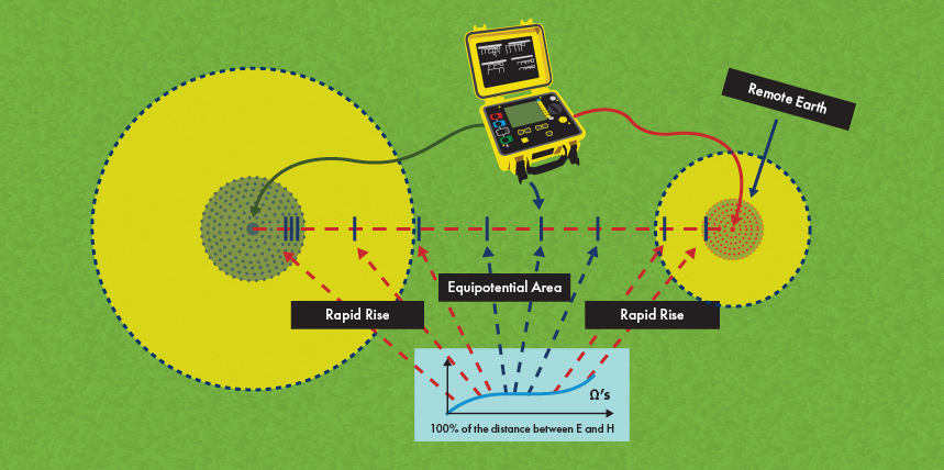
IMAGE COURTESY OF AEMC® INSTRUMENTS
In many cases, the required distance can extend several hundred feet, such as when a technician must execute FOP measurements related to transmission and distribution infrastructure and installations. This creates practical challenges, particularly in developed areas where space is limited or obstructed by infrastructure. Additionally, longer test distances may approach the operational limits of the test instrument, particularly in high-resistance soils where sufficient current injection becomes more difficult.
These constraints are further compounded when the test path must traverse paved or otherwise inaccessible surfaces. Modern facilities are often constructed with extensive paved areas, including parking lots, access roads, walkways, and equipment pads. These surfaces can severely limit the ability to place electrodes at the required intervals.
In some cases, technicians may be able to reroute the test path to reach exposed soil, but such adjustments are not always possible without compromising the geometry of the test. When proper spacing cannot be achieved, the validity of the results may be called into question.
To address this issue, alternative electrode techniques can be used to establish effective electrical contact through paved surfaces. These methods rely on the inherent properties of asphalt and concrete to facilitate current flow when properly conditioned.
Blacktop and Pie Plates
Asphalt concrete (hereafter referred to as asphalt) offers a relatively forgiving medium for alternative testing methods. Asphalt is composed of bitumen—a viscous, petroleum-based binder—and aggregate such as crushed stone and sand. It is typically installed over compacted sublayers that provide structural support.
While new asphalt is largely impermeable, it becomes increasingly porous over time due to environmental exposure, wear, and microfracturing. This permeability allows liquids to penetrate the surface, creating a conductive path when combined with a suitable electrolyte.
The flat electrode method takes advantage of this property. Instead of driving a stake, the technician uses a flat conductive plate—at minimum, the size of a nine-inch, uncoated aluminum pie plate—combined with an electrolyte solution to simulate a ground contact.
The electrolyte solution is also critical. Its purpose is to introduce free ions into the contact area, enabling current flow between the test instrument and the underlying material. While a variety of mixtures can be used, care should be taken to ensure compatibility with the site environment. In some cases, readily available liquids such as sports drinks, lemonade, or even iced tea can provide acceptable conductivity.
A reliable and repeatable mixture includes:
- One part salt
- Two parts pure lemon juice
- Seven parts water (tap water is preferable due to its mineral content)
To perform the test, the technician applies a generous amount of the electrolyte solution to the measurement location and allows it to soak into the asphalt surface. Depending on the condition and age of the pavement, this may take several minutes.
Once the surface is adequately saturated, the flat electrode is placed on the wet area, and the walking electrode lead is connected. The technician then stands on the plate to ensure firm, consistent contact during measurement.
Success with this method depends on maintaining even pressure and ensuring sufficient saturation. When properly executed, the flat electrode method can produce results comparable to those obtained using traditional driven stakes.
Chicken Wire and Ufer Soup
Cement concrete (hereafter referred to as concrete) presents a more complex challenge. Unlike asphalt, well-constructed concrete is only minimally permeable and, when dry, acts as a relatively effective electrical insulator. This can isolate the test setup from the earth below, making conventional approaches ineffective.
Concrete is composed of cement and aggregate, forming a dense, durable material that is not easily penetrated without drilling. Fortunately, its electrical properties change significantly when saturated with water. Under these conditions, concrete exhibits semiconductive behavior due to ionic movement within its pore structure.
The mesh electrode method leverages this phenomenon. Instead of a small contact point, this approach uses a large conductive mesh—such as chicken wire or metal fencing—placed over a water-saturated section of concrete to create a broad contact interface. The mesh should be larger than the flat electrode used for asphalt applications. A size of approximately two feet by two feet is generally sufficient for most testing scenarios.
To perform the test, the technician saturates the target area with a substantial volume of water, typically around one gallon per square foot. Time must be allowed for the water to permeate the concrete thoroughly, which may take several minutes or longer, depending on the material.
Once saturation is achieved, the mesh electrode is laid flat on the surface, and the test lead is connected. As with the flat electrode method, the technician stands on the mesh to ensure consistent contact during measurement. This alternate electrode method can be seen in Figure 3.
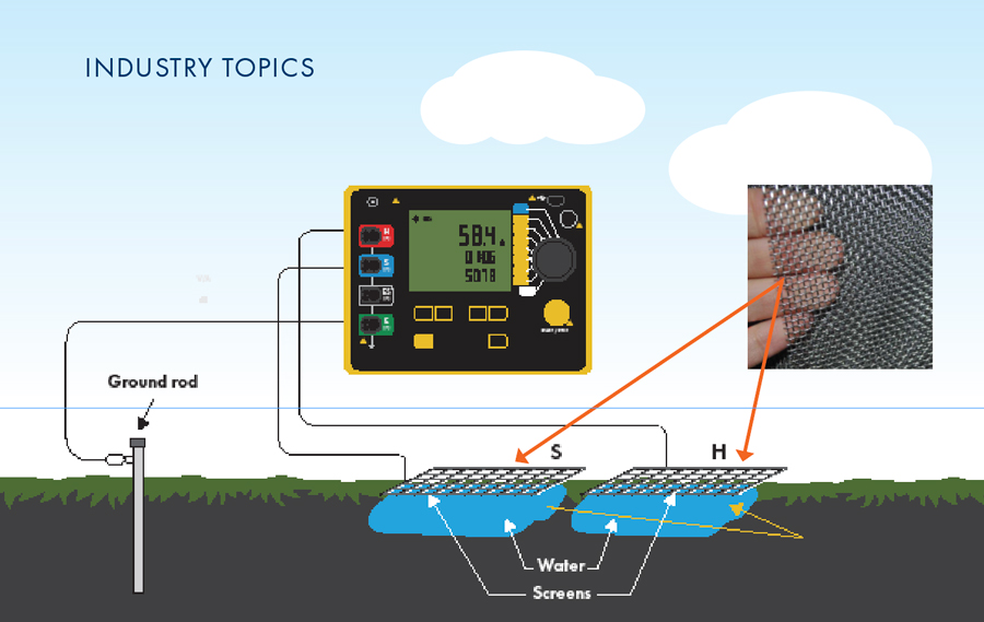
IMAGE COURTESY OF AEMC® INSTRUMENTS
It is important to note that electrolyte solutions should not be used in this method. Introducing additional ions can alter the natural conductive behavior of the saturated concrete and lead to inconsistent results.
CONSIDERATIONS AND LIMITATIONS
While these alternative techniques are effective under the right conditions, they are not universal solutions. Each method has limitations that must be understood to avoid inaccurate results or unintended consequences.
First, the use of electrolyte solutions on natural soil should be avoided. High salt concentrations can damage vegetation and alter soil chemistry, making this approach unsuitable for landscaped or environmentally sensitive areas. Moreover, a properly driven stake in loamy soil remains the most reliable and preferred method for fall-of-potential testing.
Second, both the flat and mesh electrode methods require dense, continuous substrates. Loose materials such as sand, gravel, or riprap do not provide sufficient contact or retention for water and electrolytes. In these environments, even conventional testing methods may struggle to produce stable readings. Technicians may need to drive longer rods to reach deeper, more conductive soil layers.
Finally, environmental conditions play a critical role. All ground testing relies on ionic conduction through the earth. When temperatures drop below approximately 35°F, or when subsurface layers are frozen, ion mobility is greatly reduced (Figure 4). Under such conditions, accurate testing becomes difficult or impossible, regardless of the method used.

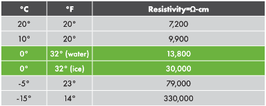
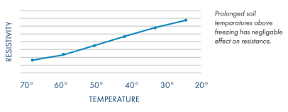
IMAGE COURTESY OF AEMC® INSTRUMENTS
FINAL THOUGHTS
Fall-of-potential testing remains one of the most reliable methods for evaluating grounding system performance, but real-world conditions rarely align with textbook assumptions. Asphalt parking lots, concrete slabs, and developed infrastructure often stand between technicians and ideal test setups.
By understanding the material properties of these surfaces and applying alternative techniques such as flat and mesh electrodes, technicians can adapt to challenging environments without sacrificing accuracy. These methods are not replacements for traditional practices, but valuable additions to the field toolkit when standard approaches are not feasible.
Ultimately, successful ground testing depends on sound judgment, attention to site conditions, and a willingness to adapt. By combining fundamental principles with practical ingenuity, technicians can continue to obtain meaningful results, no matter what lies underfoot.
REFERENCES
- IEEE Guide for Measuring Earth Resistive, Ground Impedance, and Earth Surface Potentials of a Grounding System, in IEEE Std. 81–2025, June 19, 2025.
- Korasli, C. “Ground Resistance Measurement with Alternative Fall-of-Potential Method,” 2005/2006 IEEE/PES Transmission and Distribution Conference and Exhibition, Dallas, TX, USA, 2006, pp. 942–946.
- Johannesson, B., Yamada, K., Nilsson, L-O., et al. “Multi-species ionic diffusion in concrete with account to interaction between ions in the pore solution and the cement hydrates,” Materials and Structures, Vol. 40, pp. 651–665.
- X. Ma, Q. Li, Y. C. Cui, and A. Q. Ni. (2018). “Performance of porous asphalt mixture with various additives,” International Journal of Pavement Engineering, 19(4), 355–361.

Andreas Burkart is the Technical Trainer for AEMC Instruments, manufacturer of ground resistance testers and proud NETA Alliance Partner. With more than 20 years of instructional design experience, he expertly bridges complex technical knowledge with clear, actionable training. Dedicated to NETA’s core values of safety, quality, and continuous improvement, Burkhart develops high-impact learning programs for electrical testing professionals. He is passionate about advancing industry standards for power system installation and maintenance, ensuring the highest level of reliability and dependability within the electrical power services industry.

Matt Robinson is Sigma C Power Services’s Director of Safety and Training, an adjunct professor at the Worcester Polytechnic Institute, and a student pursuing his doctorate in engineering at Penn State. His passion lies in education and development of the electrical power workforce, where he uses his position to learn as much as he can from the talented folks that make up what he considers one of the most important and poorly understood industries. Robinson holds a BS and MS in electrical engineering from Northeastern University and NETA 4 and NICET III certification, is a board-certified safety professional, and is part of NETA’s Practice Exam Committee.