
Verifying the integrity of power cable insulation is an essential step to ensure the reliability and safety of electrical systems. Applied-voltage tests are widely used before commissioning new cables and during maintenance and diagnostic activities throughout their service life. These tests enable identification of insulation defects, dielectric degradation, or installation issues that could lead to operational failures, supply interruptions, or safety hazards. Therefore, high-voltage testing constitutes a fundamental tool for assessing the dielectric condition of insulated cables in both distribution and transmission systems.
Historically, many of these tests were performed by applying direct high-voltage (DC Hipot), a practice still used in some field routines. However, N. N. Srinivas, et.al. demonstrated that applying direct voltage can induce space charge and dielectric stress in cables with extruded insulation, such as XLPE, potentially contributing to insulation degradation and reducing cable service life.
As a result, the use of alternative methods for testing cables with extruded insulation has been progressively consolidated, particularly very-low frequency (VLF) testing. These methods are currently recommended by major international technical guides, especially IEEE Std. 400.2, IEEE Guide for Field Testing of Shielded Power Cable Systems Using Very Low Frequency (VLF), which establishes procedures, voltage levels, and acceptance, maintenance, and diagnostic testing criteria for power cable systems.
The application of low-frequency alternating voltage provides better correlation with the actual operating conditions of the electrical system while also reducing the adverse effects associated with the use of direct voltage in polymeric dielectric materials. In this context, VLF testing has become a widely adopted practice for assessing the integrity of insulation in field-installed medium-voltage cables.
Regardless of the testing method used, de-energizing the system and applying voltage to insulated cables involves storing electrical energy in the distributed capacitance of the cables. As a result, electrical charges may remain trapped in the insulation after the test source is switched off or even after the circuit is de-energized prior to testing, giving rise to residual voltages.
This phenomenon has significant implications for the safety of field personnel and the integrity of connected equipment. In this context, this article addresses the mathematical modeling of the residual electric field in insulated cables subjected to applied voltage tests, explains the physical origins of residual voltage after the test source is disconnected, presents a numerical model applied to real cables, and incorporates procedures recommended by the IEEE for field testing.
RESIDUAL VOLTAGE IN INSULATED CABLES
Residual voltage in insulated cables corresponds to the electrical voltage that remains in the system after the high-voltage test source is switched off. This phenomenon is not necessarily associated with a cable failure but rather results from the storage of electrical charges in the insulation during the application of the test voltage. In power cables, especially those with polymeric insulation, a portion of this stored energy may remain in the dielectric after the source is removed, resulting in a potential difference between the central conductor and the metallic shield or grounding system.
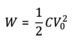
From an electrostatic perspective, the cable can be interpreted as a distributed capacitor along its length. During the high-voltage test, electrical energy is stored in the electric field within the insulation, according to the energy-storage equation of a capacitor, as shown in Equation (1). In this relationship, W represents the energy stored in the cable’s electric field, C is the cable’s equivalent capacitance, and V₀ is the voltage applied during the test.
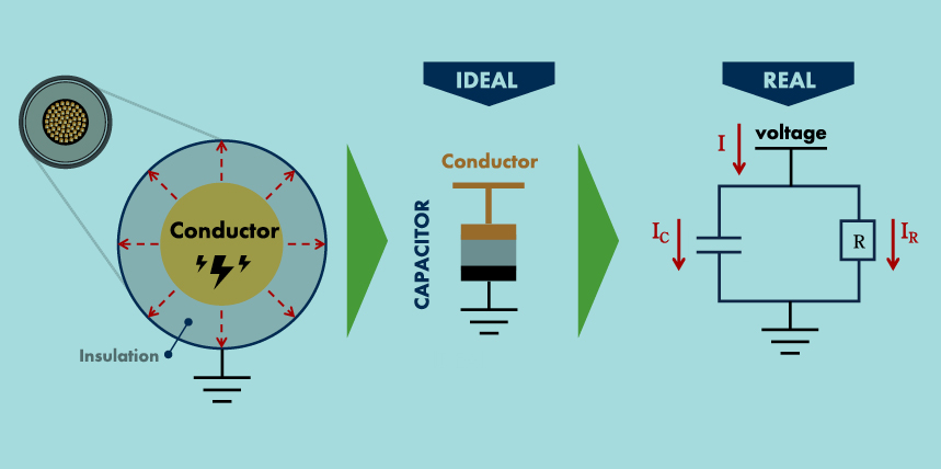
After the high-voltage source is switched off, this energy is not dissipated instantaneously, as the system has leakage resistances and dielectric absorption within the insulation. As a result, energy dissipation occurs gradually, leading to a progressive decay in voltage over time and the formation of a residual voltage in the cable.
Figure 1 illustrates this concept by presenting an analogy between the ideal behavior of the cable as a capacitor and a more realistic equivalent model, in which phenomena such as leakage currents and dielectric absorption influence the dissipation of the stored energy.

Figure 1: This graphic is a conceptual representation of an insulated cable as a distributed capacitor and the equivalent circuit associated with the residual voltage phenomenon.
Polymeric insulating materials used in power cables, such as cross-linked polyethylene (XLPE), exhibit dielectric absorption due to slow polarization mechanisms and the trapping of space charges within the material. During voltage application, molecular dipoles and charge carriers may align or move in response to the electric field, storing energy in the dielectric. After the voltage source is removed, this process does not reverse instantaneously, and it is characterized by an electrical relaxation regime with multiple time constants (τᵢ).
As a result, the voltage decay in the cable does not follow a purely exponential behavior. Under certain conditions, part of the previously stored charge may redistribute internally after the initial discharge, giving rise to the phenomenon known as voltage rebound.
Some factors increase the risk associated with residual voltage:
- Long cables. The greater the length, the higher the total capacitance C, and therefore the greater the stored energy. For example, 35-kV cables longer than 1 km may accumulate more than 100 joules, which is sufficient to produce an electric arc or an electric shock.
- High test voltages. The stored energy increases with V₀²; therefore, tests performed at 2U₀ or 2.5U₀ significantly increase the associated risk.
- Cables with extruded insulation (XLPE, EPR). Slow polarization and charge trapping mechanisms cause residual voltage to persist for minutes or even hours.
- Inadequate termination or connection conditions. Open or poorly grounded terminations allow residual voltage to lead to electric arcs or shock hazards. Connections near relays, transformers, or electronic equipment may also be damaged.
MATHEMATICAL MODELING OF THE ELECTRIC FIELD
For the quantitative analysis of the phenomenon, the insulated cable is modeled as a coaxial geometry, consisting of a central conductor and a metallic shield separated by insulation that serves as the dielectric. In this model, a represents the conductor radius, b corresponds to the inner radius of the shield, L is the cable length, and ε is the electrical permittivity of the insulating material, defined as ε = ε₀εᵣ, where ε₀ is the vacuum permittivity and εᵣ is the relative permittivity of the dielectric.
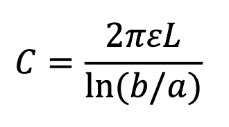
From this coaxial geometry, the total capacitance of the cable is obtained, as presented in Equation (2), which depends on the permittivity of the insulating material, the cable length, and the ratio between the shield radius and the conductor radius. This parameter is fundamental for analyzing energy storage in the system, since the total capacitance C appears directly in the expression of the electrical energy stored in the cable during the voltage test, as previously presented in Equation (1).
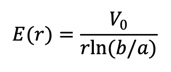
When a voltage V₀ is applied between the conductor and the shield, a radial electric field is established within the insulation. The intensity of the field varies with the radial distance r from the conductor’s center. This electric field is described by Equation (3), in which E(r) represents the electric field intensity at a point located at a radial distance r from the cable axis, V₀ corresponds to the voltage applied during the test, a is the conductor radius, and b is the inner radius of the shield.
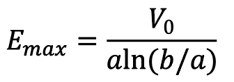
The electric field distribution is not uniform across the insulation, being more intense in regions close to the conductor. Therefore, the maximum electric field, indicated in Equation (4), occurs at the interface between the conductor and the insulating material, when r = a. This result is particularly relevant for the analysis of dielectric stress in the cable, since this is the region where the insulation is subjected to the highest electric field level during voltage application.
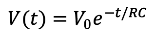
After the test source is removed, the voltage in the cable does not instantaneously drop to zero but instead decays over time due to energy dissipation in the system. In a simplified approach, this behavior can be described by the equivalent RC model of the cable, in which the voltage decay follows an exponential function over time, as represented in Equation (5), where V(t) corresponds to the voltage at time t, V₀ is the initial voltage at the moment the source is disconnected, R represents the equivalent leakage resistance, and C is the cable capacitance.
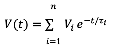
However, in polymeric dielectric materials, such as XLPE, used in power cables, additional phenomena associated with dielectric absorption and slow polarization are observed and are not fully described by a single RC circuit. In such cases, the residual voltage behavior can be represented as a sum of multiple exponential terms with different time constants (τᵢ), as shown in Equation (6). This more comprehensive model explains phenomena observed in practice, such as the partial reappearance of voltage after an initial discharge, known as voltage rebound.
Example 1 — 15-kV Cable (8.7/15-kV Class)
For the first example, a medium-voltage cable of class 8.7/15-kV is considered, subjected to an acceptance test using VLF voltage, a method widely employed in field testing to assess the integrity of insulation in cables with polymeric dielectrics such as XLPE or EPR. In systems of this class, the nominal phase-to-ground voltage is U₀ = 8.7 kV. During acceptance testing, IEEE guides typically recommend applying 2U₀, resulting in a test voltage of V₀ = 17.4 kV. The typical parameters used to estimate the energy stored in the cable are presented below.
- Cable length: 1 km
- Typical capacitance: 0.20 µF/km
- VLF test voltage (acceptance): 2.0 U₀
The energy stored in the cable during the test can be estimated using the capacitor energy equation, Equation (1). Considering the total capacitance corresponding to 1 km of cable and the applied test voltage, substituting these values into Equation (1) results in the expression presented in Equation (7).

This result indicates that, even for a single kilometer of a medium-voltage cable, the electrical energy stored during the test can reach several tens of joules. Values of this magnitude are sufficient to produce a perceptible electrical discharge, an electric arc, or a potentially hazardous shock if the cable is handled before the complete dissipation of the stored energy after the end of the test.
Example 2 — 35-kV Cable (20/35-kV Class)
For the second example, a medium-voltage cable of class 20/35-kV is considered, also subjected to an acceptance test using VLF voltage. In this class of system, the nominal phase-to-ground voltage is U₀ = 20 kV. By applying 2U₀, the test voltage becomes V₀ = 40 kV. The typical parameters used to estimate the energy stored in the cable during the test are presented below.
- Cable length: 1 km
- Typical capacitance: 0.18 µF/km
- VLF test voltage (acceptance): 2.0 U₀
By again applying the capacitor energy Equation (1) and considering the total capacitance for 1 km of cable, the value in Equation (8) is obtained.

This result shows that, for higher-voltage-class cables, the energy stored during the test increases significantly, reaching hundreds of joules. Levels of this magnitude represent a substantial risk of electrical discharge, arcing, or severe shock if the cable is handled before proper discharge and grounding procedures are carried out after the test.
RECOMMENDED OPERATIONAL PROCEDURES
1. Before the Test:
a. Verify absence of voltage using a voltage absence detector.
b. Discharge the cable using a discharge rod suitable for the operating voltage level, maintaining it for the minimum calculated time.
c. After resistive discharge, apply direct grounding and keep it connected.
d. Disconnect any equipment that may influence residual voltage.
2. During the Test:
e. Apply the voltage in accordance with IEEE Std. 400.2 guidelines.
f. Monitor current and resistance, if the test equipment includes measurement capabilities.
3. After Voltage Application:
g. Discharge the cable using a discharge rod suitable for the test voltage level, maintaining it for the minimum calculated time.
h. After resistive discharge, apply direct grounding and keep it connected.
i. Measure the residual voltage before allowing access to the circuit.
j. It is recommended to maintain discharge and grounding applied for a duration equivalent to multiple time constants (≥ 5τ = 5RC).
CONCLUSION
Residual voltage in insulated cables subjected to high-voltage testing is an inherent physical phenomenon associated with the capacitive behavior of the system and the polarization mechanisms present in dielectric materials. During voltage application, electrical energy is stored in the distributed capacitance of the cable and within the insulation dielectric. After the test source is removed, this energy is not dissipated instantaneously and may temporarily remain in the system as residual voltage.
The mathematical modeling presented in this work demonstrates that the behavior of residual voltage can initially be described by an equivalent RC model, in which the voltage decays exponentially over time. However, in cables with polymeric insulation, such as XLPE or EPR, additional phenomena, including dielectric absorption and slow polarization, introduce multiple time constants into the electrical relaxation process. This behavior may lead to partial voltage recovery (voltage rebound) after an initial discharge, underscoring the need to consider more comprehensive models when analyzing the phenomenon.
The numerical examples presented for 15-kV and 35-kV cables show that the energy stored during VLF testing can reach tens or even hundreds of joules, even in relatively short cable lengths. Values of this magnitude are sufficient to produce perceptible electrical discharges, electric arcs, or potentially hazardous shocks if the system is handled before the stored energy is completely dissipated.
From an operational standpoint, these results reinforce that the presence of residual voltage should not be interpreted as an insulation failure but rather as a natural consequence of the cable’s electrostatic behavior. Nevertheless, it represents a real risk to personnel and equipment if proper discharge and grounding procedures are not followed.
In this context, the safe management of residual voltage must be treated as an integral part of high-voltage testing procedures. Recommended practices include controlled cable discharge with appropriate resistors, temporary grounding after testing, verification of the absence of voltage with suitable instruments, and the application of operational safety procedures, such as lockout/tagout (LOTO). These measures, aligned with IEEE technical guides and safety standards such as NFPA 70E, are essential to ensure the safety of field personnel, the integrity of equipment, and the reliability of test results.
REFERENCES
- N. N. Srinivas, B. S. Bernstein and R. A. Decker. “Effects of DC testing on AC breakdown strength of XLPE insulated cables subjected to laboratory accelerated aging,” IEEE Transactions on Power Delivery, vol. 5, no. 4, pp. 1643-1651, Oct. 1990, doi: 10.1109/61.103658.
- IEEE Guide for Field Testing of Shielded Power Cable Systems Using Very Low Frequency (VLF) (less than 1 Hz), in IEEE Std. 400.2-2024 (Revision of IEEE Std. 400.2-2013), pp.1-54, 27 Sept. 2024, doi: 10.1109/IEEESTD.2024.10694771.
- IEEE Guide for Field Testing and Evaluation of the Insulation of Shielded Power Cable Systems Rated 5 kV and Above, in IEEE Std 400-2023 (Revision of IEEE Std 400-2012), pp.1-54, 17 Nov. 2023, doi: 10.1109/IEEESTD.2023.10336851.
- EEE Guide for Partial Discharge Field Diagnostic Testing of Shielded Power Cable Systems, in IEEE Std. 400.3-2022 (Revision of IEEE Std. 400.3-2006), pp.1-63, 15 May 2023, doi: 10.1109/IEEESTD.2023.10123370.
- IEEE Guide for Field Testing of Shielded Power Cable Systems Rated 5 kV and Above with Damped Alternating Current (DAC) Voltage, in IEEE Std. 400.4-2015, pp.1-62, 29 Jan. 2016, doi: 10.1109/IEEESTD.2016.7395998.
- NFPA 70E, Standard for Electrical Safety in the Workplace, 2024 ed., Quincy, MA, USA, 2024.
- NFPA 70, National Electrical Code, 2026 ed., NFPA, Quincy, MA, USA, 2025.

Nilson Baroni Jr., PMP, is currently the Operations Director of BAUR USA Corp. He is a Senior Electrical Engineer with more than 34 years of experience leading teams and managing projects in the engineering, operations, and maintenance of low-, medium-, and high-voltage electrical networks in the overhead and underground segments in the largest electric utility in Brazil. Baroni is an experienced international speaker on topics related to electric utilities.

Daniel Bento, PMP, is the CEO of BAUR do Brasil and BAUR USA Corp. He is an Electrical Engineer with more than 30 years of experience in medium-voltage insulated cable networks. He is a former coordinator of CIGRE Study Committee B1 on insulated cables and co-author of CIGRE Technical Brochures 773 and 924 on fault location and cable diagnostics. He was the technical lead for the entire underground distribution network in São Paulo, Brazil.

Danilo de Souza is an Associate Professor at the Federal University of Mato Grosso (UFMT), working in electrical safety, energy efficiency, and energy planning. He supervises master’s and doctoral research at both UFMT and USP. He is a member of the technical standards committees of the Brazilian Association of Technical Standards (ABNT). De Souza holds a Ph.D. in Energy from the University of São Paulo (USP).

Marcelo Plantier currently works as an Application Engineer at BAUR do Brasil, providing technical support, training, and solutions for high-voltage testing and diagnostic equipment. He is an Electrical Engineer specializing in power electrical systems, with 8 years of experience in testing and diagnostics of underground insulated power cables, as well as maintenance of electrical power equipment.