
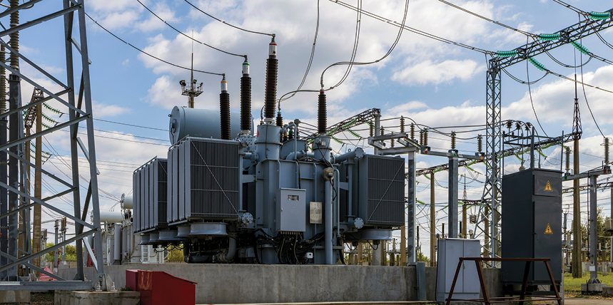
This paper analyzes the ground differential or restricted earth fault (REF) element for transformer protection and compares its performance against various levels of current transformer (CT) error and saturation. An empirical analysis was performed to determine the limits of today’s common digital relays as they experience CT errors. This can help engineers develop general guidelines for designing protection systems related to REF elements. The impact of auxiliary CTs was also examined to determine their influence on element performance. Finally, a real-world misoperation of the REF element due to CT error was evaluated to provide solutions to prevent similar issues.
REF PROTECTION AND TYPICAL PROTECTION CHARACTERISTICS
At its core, ground differential (87G) protection (REF) is comparable to other current differential protection schemes, where CT placement defines the internal protection zone. However, the value of transformer REF protection is its sensitive detection of ground faults near the neutral of a grounded wye winding. These faults can produce large and damaging circulating currents with minimal impact on the associated phase currents used in conventional transformer phase-percentage differential protection.
To provide protection coverage at the lower end of the transformer wye windings, the REF element commonly uses the transformer neutral current (IN) and the associated transformer terminal bushing or breaker residual current (3I0) via wye-connected CTs. These CTs ultimately define the selective protection zone of this element, and knowing the polarity and phase-angle relationships of the configured CTs can provide a secure method to distinguish between internal and external faults. For this reason, REF elements can provide more sensitive detection of ground faults near the transformer neutral than conventional transformer phase-percentage differential protection, helping to prevent catastrophic fault evolution.

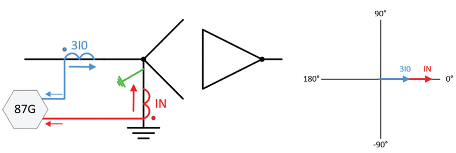
Typical differential CT configurations where polarity faces away from the protected equipment are shown in Figure 1. Assuming no CT saturation, the ideal phase difference between 3I0 and IN is 180 degrees for any external ground current condition. In addition, the 3I0 and IN primary current magnitudes should closely resemble each other.
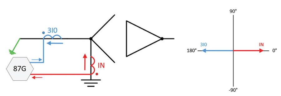
For internal ground faults on the protected winding, the phase difference between 3I0 and IN for the mentioned CT configuration should be closer to 0 degrees. However, unlike external faults, 3I0 and IN primary current magnitudes may vary for internal faults, as the fault sources and impedance to the fault location will be different. Figure 2 and Figure 3 illustrate these correlations for internal and external ground faults based on the CT configuration. These CT relationships, combined with varied vendor algorithms, define the basics of REF protection.
TESTING REF ELEMENT CHARACTERISTICS
Four microprocessor relays from various manufacturers were tested in a laboratory environment to determine typical REF element characteristics by applying a residual and neutral current with an angle difference of 0 to 180 degrees. The relays were configured to trip with no delay when the difference between the angles was minimal and restrained when the polarity was opposite.
While each manufacturer’s relay operated with varying algorithms, the authors attempted to configure the relays with typical and similar settings for comparison. While Relay #1 and Relay #2 provide directional supervision of the element limited to an angular range, Relay #3 and Relay #4 operate on a percentage differential concept where the slope percent defines the angular area of operation. The REF operating characteristics were additionally normalized for a one-per-unit current pickup for comparison between relays.
If the transformer neutral IN current is set as the reference angle, an external fault occurs when the residual 3I0 current is 180 degrees out of phase and should not result in a REF trip. CT error on the phase CTs results in an angular change to the 3I0 current as it is processed through a microprocessor relay filtering algorithm, shown as the dashed phasor in Figure 4. If the angle change of the residual 3I0 current due to CT error is severe enough, the filtered signal may cross into the internal fault region and misoperate.
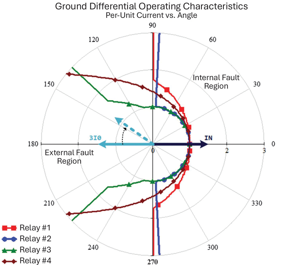
Laboratory testing confirmed that the REF element is very secure against single-line-to-ground (SLG) through-faults regardless of the degree of saturation simulated for phase CT inputs. Severe phase CT saturation resulted in a filtered current around 60 degrees offset from an ideal non-saturated signal. Other field events have shown that heavy neutral CT saturation can cause a shift of 45 degrees, but would not be able to shift by more than 90 degrees, which highlights the security of the directionally supervised REF elements.
SOURCES OF CT ERROR
Any protection system requires proper design and analysis to ensure an effective system. Protection engineers are often faced with limitations that require balancing dependability and security. One example related to transformer protection is replacing an electromechanical (EM) relay with a microprocessor relay. EM transformer differential relays typically do not perform internal compensation for angle shifts produced by the transformer configuration and can require external compensation. For example, a delta-wye transformer protected by an EM differential relay can have CTs wired as wye on the delta side and delta on the wye side to compensate externally for angle shifts. Additionally, auxiliary CTs can be used to help normalize or compensate for the current entering the relay.
As microprocessor relays can numerically compensate for magnitude and angle shifts internally, best practice is to wire CTs directly to the relay in a wye configuration with no intermediate auxiliary CTs. This configuration limits the impedance seen by the system CTs for some fault types, which can reduce CT error. However, a spare CT wire might not be available to convert the three-wire delta configuration to a four-wire wye configuration. Similarly, removing a set of auxiliary CTs in a relay circuit may require installing new wiring at high cost.
A protection engineer must be well-versed in analyzing CT performance when considering the protection system. One popular resource is the CT Saturation Theory and Calculator Excel spreadsheet provided by the IEEE Power System Relaying Committee. However, the performance of auxiliary CTs may not be readily known, as the data, if it were originally available, may have been lost over the years.
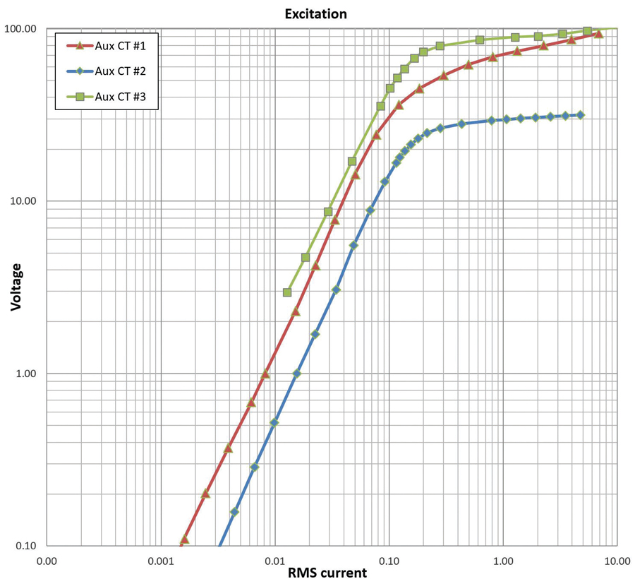
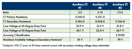
The authors were unable to track down factory performance data for most in-service auxiliary CTs. Instead, two common auxiliary CT types used for protective relaying were selected. The nameplate data for these auxiliary CTs provided little information beyond the current ratio. Various CT tests were performed to help understand typical auxiliary CT performance as seen in Table 1 and Figure 5. Auxiliary CT #3 was not available for testing, but factory-provided excitation curves and details had been saved from over 50 years ago.
In an additional test on Auxiliary CT #1, the secondary side was loaded with a 10-Ω resistor, and a 10-A symmetrical signal was injected. This required the CT to produce a 100-V secondary, which would be above the CT’s capability shown in Table 1. The input signal can be seen in Figure 6 as 1:CT_INPUT. The initial output on the secondary side of the auxiliary CT can be seen as 1:CT_OUTPUT with characteristic saturation.
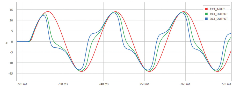
The authors were curious how the auxiliary CT would respond to a saturated signal as an input, so the 1:CT_OUTPUT signal was replayed back into the CT, with the resulting 2:CT_OUTPUT as the twice-saturated signal measured on the secondary. During CT or event analysis, it may be of benefit to consider one or both primary and auxiliary CTs saturating differently depending on the input signal, level of DC offset, and any remanent flux in the CT.
Once the auxiliary CT performance data is known, it can be analyzed along with the primary CT with respect to the system configuration for transient performance as seen in Hargrave et al.
MISOPERATION EVENT ANALYSIS
The configuration of the transformer relay that misoperated is shown in Figure 7. This microprocessor relay replaced a prior EM percentage-restraint transformer protection relay set with no existing REF protection. Dual relays were installed, providing duplicate protection through the same CT circuits for all elements except the REF element. The A-set relay was wired to the 161-kV neutral, and the B-set was wired to the 46-kV neutral. The 46-kV phase and neutral auxiliary CTs that remained in the secondary circuit were then incorporated into the new 46-kV REF element.
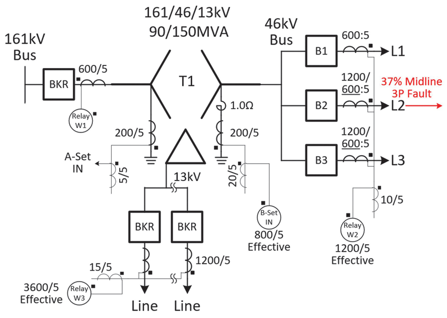
The transformer is a bank of three single-phase transformers; however, the neutral currents are bussed together with a single ground point through a 1-Ω reactor and a single neutral CT. Configurations that sum three neutral CTs from each single-phase transformer require advanced techniques for REF protection. The primary-phase CTs on the 46-kV breakers are all rated at C800, but the faulted line CT is tapped at half the ratio due to the single ratio 600/5 CT associated with Breaker B1, making the CT associated with Breaker B2 an effective C400 rating. A confirmed three-phase fault occurred around 37% down the 46-kV L2 line. While the L2 breaker tripped, the transformer 46-kV REF element operated before the L2 breaker cleared the fault.
The 46-kV B-phase current (W2_IB) shows signs of CT saturation for the first two cycles of the event in Figure 8. The filtered current magnitudes show that the B-phase current was about 10% lower than the other phases when saturated, but 10% higher when not saturated. It is common to think of three-phase faults as perfectly balanced, but system asymmetries can create imbalance and ground current, as shown in this event. In this case, the 46-kV auxiliary B-phase CT had an input signal of about 44 A with some DC offset and was expected to produce 22 A. As the auxiliary CT was mounted above the relay, the leads between the auxiliary CT and the relay could be considered to have negligible impedance. The microprocessor relay CT inputs also have little burden.
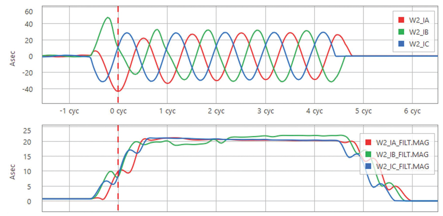
Based on the system model, a similar fault resulted in an estimated X/R ratio of about 5. An impedance of 0.1 Ω would result in an auxiliary CT secondary voltage requirement of under 20 V, assuming no remanent flux in the CT. If the long lead connection from the field and the auxiliary CT primary impedance resulted in a total impedance of 1.6 Ω, the primary CT would need to support a secondary voltage above the 400-V rating. Regardless of whether the primary or the auxiliary CT saturated, this configuration is not ideal and warrants additional security measures for relay protection associated with the 46-kV currents.
The resulting filtered and unfiltered neutral and residual (3I0) 46-kV currents can be seen in the top two graphs in Figure 9. At the beginning of the event, the CT saturation results in a filtered 3I0 that is within 40 degrees of the neutral current, indicating an internal REF trip condition.
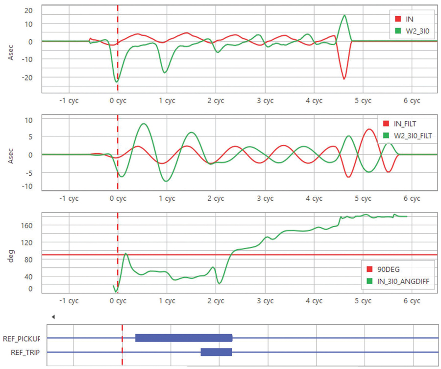
Once the saturation subsides, the angle difference moves to 180 degrees away from the neutral current past the 90-degree threshold, indicating an external through-fault condition. The REF element was also configured to block operation when the neutral current was below 1.2 Asec or the phase residual current was below 0.96 Asec. These thresholds align with a typical 10% imbalance for the transformer MVA rating. During the initial saturated portion of the event, the neutral current measured around 1.9 Asec, and the phase residual current measured 6.0 Asec, permitting the REF element to operate.
Since this misoperation occurred, the breaker with the 600/5 CT was replaced and now supports a 1200/5 ratio. The 10/5 auxiliary CT on the 46-kV phase currents was removed. Whether the cause of the misoperation was the primary or auxiliary CT, no issues have occurred since the reconfiguration to remove the auxiliary CTs and use a 1200/5 primary CT ratio.
SIMULATION AND TESTING
To better understand how the REF element responds to CT saturation and multi-phase-ground faults, a series of simulated signals was created and played back through a relay configured to operate when the angle difference between the phase-residual and neutral current was less than 90 degrees. The IEEE CT Saturation and Theory spreadsheet was used as the basis for creating a signal that generated an ideal and saturated A-phase current. The spreadsheet was modified to generate an additional ideal B-phase current and the resulting ideal neutral current. No current was applied to the C-phase, as it is assumed to be zero for this phase-phase-ground fault type. The magnitude of the B-phase current was set to 95% of the ideal A-phase current, and the B-phase angle was set around 155 degrees. The selection of this angle was derived from the system model by applying a phase-phase-ground fault at the same location as the analyzed event. The resulting signals with no CT error can be seen in Figure 10 with the residual IG current 180 degrees out from the neutral IN current. For this event, the REF element restrains, as IG is 180 degrees from the reference IN.
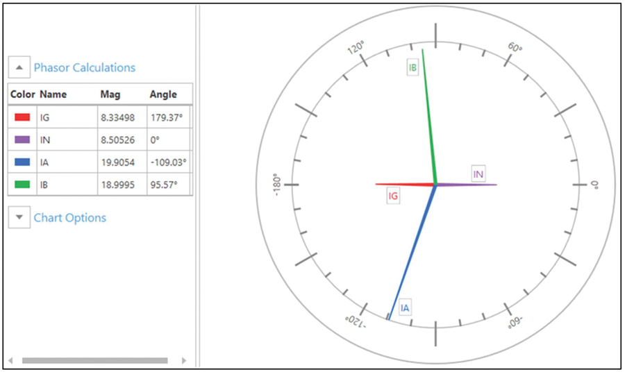
As the A-phase current saturates, the filtered magnitude reduces, but more importantly, the filtered phase angle leads the ideal current. The latter portion of the positive or negative sinusoid waveform is reduced during saturation, so the peak looks to occur earlier in the filtered waveform, resulting in the leading phase angle. As a CT with an ideal sinusoid input saturates further, the filtered signal peak could shift by only 90 degrees before it crosses into the opposite polarity region. This highlights the security of REF elements set with a 90-degree characteristic angle for single-phase faults.
When the angle between IA and IB increases beyond 180 degrees due to CT error, the resulting filtered IG angle quickly moves to less than 90 degrees from IN and into the internal REF trip region (Figure 11). One consideration when analyzing CT saturation and phase-phase-ground faults with REF elements is that less CT saturation is required for a misoperation to occur as the angle separation between the two faulted phases increases. For instance, with a 120-degree separation, one phase would need to saturate such that the filtered waveform would shift by over 60 degrees to misoperate. The simulation in this section shows a 155.4-degree separation, which would require the resulting filtered waveform to shift by only 25 degrees for a REF misoperation.
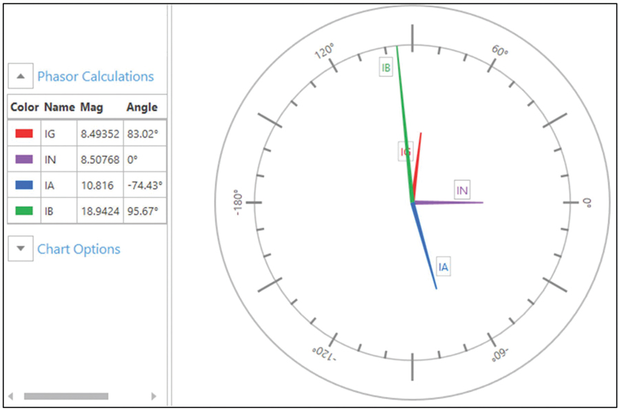
A simple cosine filter model was created to perform relay simulation for unbalanced three-phase faults. Like the fault analysis in the previous section, a three-phase fault with a single phase 10% higher than the others and various levels of saturation was analyzed. When A-phase CT saturates, the missing current creates a large spike in the opposite direction when residually summed to the ground signal (Actual IG in Figure 12). When this signal is filtered, the resulting angle can cause a REF operation with small amounts of CT saturation.
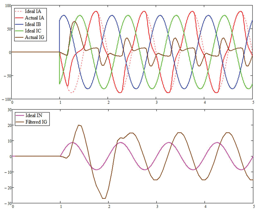
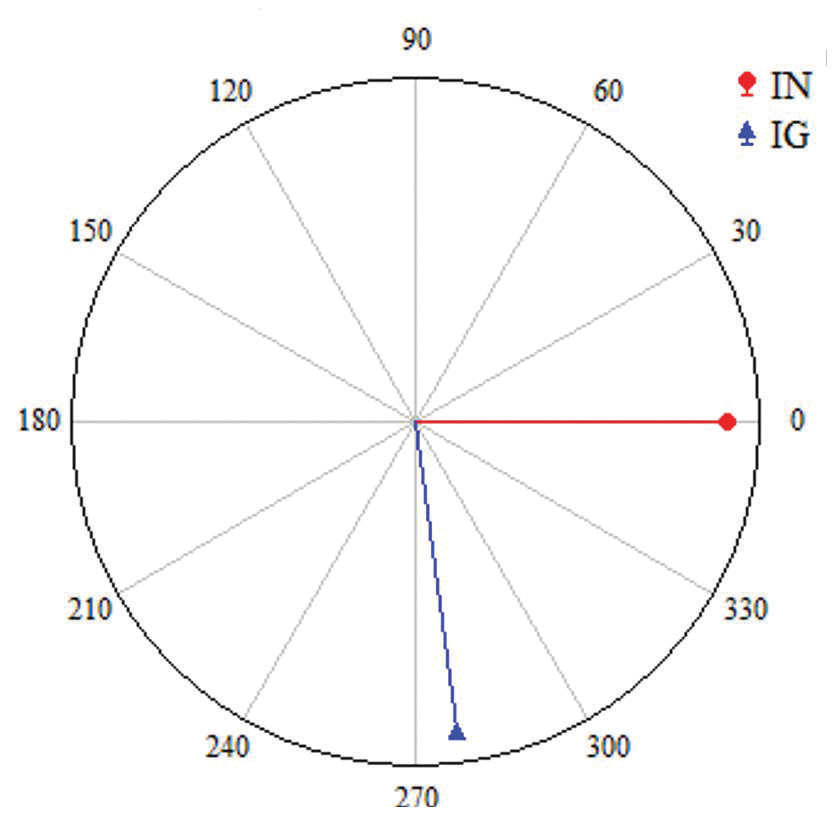
Figure 12 shows CT saturation on the A-phase and the resulting residual IG current on top. The bottom of Figure 12 shows the neutral current IN and the filtered residual IG current. The phasor diagram in Figure 13 from the latter portion of the waveform shows that the angle difference between IG and IN is less than 90 degrees and is in the REF trip region for the waveforms in Figure 12.
Analyzing the waveforms in Figure 12 graphically shows that an unbalanced three-phase through-fault may be more susceptible to REF misoperation due to saturation than a phase-phase-ground through-fault. Both fault types should be considered when designing the REF protection for a transformer if CT saturation is expected.
CHALLENGES AND GUIDELINES FOR REF PROTECTION
When REF misoperations occur, neutral CT polarity is often the cause due to the complexity of properly designing or testing the scheme. CT polarity requirements may vary between relay manufacturers, which can create misunderstanding in the design. Performing 100% testing of the neutral CT polarity to the relay may therefore require alternate test methods, such as primary current injection or analysis of event records triggered by nearby ground faults. While the REF element has shown to be secure for single-phase-ground through-faults, multi-phase-ground through-faults warrant additional analysis.
If CT analysis shows the system may have CT saturation issues for multi-phase-ground faults and physical changes to the system are not available, additional protection security can be implemented. For the fault described in the previous analysis section, negative-sequence blocking logic or a short time delay could have prevented the misoperation.
Another consideration is to increase the REF current magnitude threshold. Calculations showed that increasing the REF neutral current magnitude threshold from 192 Apri to 300 Apri (10% to 17% of the nominal transformer rating) would have also prevented this REF trip. Das et al discuss the percentage of the winding that is protected by REF by changing the current pickup level, which would reduce the transformer winding protection from 99.3% to 98.9% with the higher current pickup in this case. Das also discusses more advanced security techniques, including blocking the REF element with negative-sequence current to address multi-phase-to-ground through-faults.
From the authors’ experiences with fault analysis and testing, a few guidelines can be considered:
- Ensure the design of the CT polarities for the protection system being considered is understood.
- Perform a fault study for phase-phase-ground and three-phase through-faults to determine if CT saturation is applicable for either the phase or neutral CTs, including any auxiliary CTs. Note that a large angle separation between faulted phases on a phase-phase-ground through-fault may require little CT error for a REF misoperation.
- If CT saturation for the above fault types is of concern, additional security to the REF element may be needed. Increased security options include:
a. Consider newer protective relays that can block REF protection based on comparisons of positive- and negative-sequence currents to the residual zero-sequence current to detect CT saturation during a through-fault condition. This blocking logic can also be achieved through custom logic schemes.
b. Reduce the sensitivity of the element by increasing the current magnitude pickup. This will reduce the total coverage of the transformer winding. If the REF element is based on a slope characteristic, increasing the slope can also accommodate larger angle shifts.
c. Add a time delay or inverse time-overcurrent characteristic to ride through any transient CT error conditions.
SUMMARY
While the transformer REF element is typically secure for single-phase faults, event analysis and laboratory testing have shown that the element is susceptible to misoperation during unbalanced multi-phase-ground through-faults if one of the phase CTs saturates. Fault studies can be performed to ascertain the data associated with these fault types to verify CT performance. This article has presented a real-world REF misoperation event, how it was redesigned, additional considerations to increase security if those hardware changes were not available, and guidelines to help the reader determine when more in-depth analysis is warranted.
ACKNOWLEDGEMENT
The authors thank the Electrical Engineering Department at the University of Tennessee at Chattanooga for the use of its Smart Grid Laboratory to carry out the testing described in this article.
REFERENCES
M. Kao, G. Kobet, G. Pitts. “Considerations and Experiences in Implementing Ground Differential Protection for Transformer Protection at TVA,” presented at the 63rd Georgia Tech Protective Relaying Conference, 2009.
R. Patterson. “Pinhook 500-kV Transformer Neutral CT Saturation,” presented at the 9thGeorgiaTechFaultand Disturbance Analysis Conference, May 1–2, 2006.
IEEE Power & Energy Society. “CT Saturation Theory and Calculator,” Power System Relaying and Control Committee Knowledge Base Report, PES-PSRC.org, 2003.
A. Hargrave, M. Thompson, B. Heilman. “Beyond the Knee Point: A Practical Guide to CT Saturation,” presented at the 71stTexasA&MUniversityAnnualConferenceforProtectiveRelayEngineers, March, 2018.
S. Das, A. Hargrave, M. Taberer, M. Thompson. “A Call to Action: Say YES to Restricted Earth Fault Protection,” presented at the 76thTexasA&MUniversityAnnualConferenceforProtectiveRelayEngineers, March, 2023.

Seth Barnes joined the Tennessee Valley Authority in 2013 and worked as a Telecomm Field Engineer and later a System Engineer in the North Alabama area. He joined the System Protection & Analysis Group in 2017, where he develops relay settings and performs post-fault event analysis for the TVA power system. A member of IEEE, Barnes graduated from the University of Mississippi with a BS in electrical engineering and earned an MS in electrical engineering from the University of Tennessee at Chattanooga. After graduating, he worked as a contract Telecomm Engineer for AT&T in Mississippi.

Tim Condra is an Electrical Engineer in the Tennessee Valley Authority’s (TVA) System Protection and Analysis Division. His responsibilities include calculating and engineering protective settings and logic across TVA’s fleet of relaying devices, as well as diagnosing and troubleshooting operating issues with existing protective equipment. Condra is also responsible for analyzing all TVA transmission operations to determine correct or incorrect equipment operation. He earned a BS in electrical engineering from Tennessee Technological University with a focus on power systems.

Joshua Hughes is a Principal Engineer at Qualus, focused on system studies, field system protection services, event root-cause analysis, and technical training. He initially worked as a System Engineer at Tennessee Valley Authority nuclear substations, providing commissioning services, root cause analysis, and system data trending to predict equipment failures. Hughes previously worked at Schweitzer Engineering Laboratories, where he served as a Project Engineer and Senior Application Engineer, providing application and product support, and technical training for protective relay users. Hughes is an IEEE Senior Member and a registered Professional Engineer in the state of Tennessee. He graduated from Tennessee Technological University with a BS in electrical engineering with a focus on digital signals.

Akram Saad is a Principal Engineer with Quanta Technology and an Adjunct Faculty with the University of Tennessee at Chattanooga, where he teaches a Setting and Testing Digital Relays class. He received a BSc in electrical engineering from the University of Khartoum, Sudan, in 2014 and an MScinelectricalengineeringinAugust2018from the Universityof TennesseeatChattanooga, whereheworkedas a graduate assistant at the Department of Electrical Engineering for two years. Saad worked as a protection and design consultant at Patterson Power Engineers from 2018 to 2021. He has authored and co-authored five papers and holds one U.S. patent.