

Voltage dividers are simple devices consisting of series circuits that produce two or more lower voltages from a single source voltage via resistances. This is possible because of this mathematical fact: Given a series circuit with multiple resistances, the sum of the absolute values of all voltage drops across each resistance will equal the source voltage.
This fact is illustrated most conspicuously in voltage sensors. Voltage sensor instruments are an alternative to potential transformers. They are installed to report high voltages for metering or protection purposes. Suppose a protection and control (P&C) engineer needs a device capable of reporting a 50-kV phase-to-ground voltage safely to a metering or protection relay. A single-bushing potential transformer could be deployed to do the job. As an alternative, they could install a voltage sensor.
CASE STUDY
Suppose this 50-kV voltage sensor contained two serial resistors, one 50 MΩ and one 50 kΩ (Figure 1).
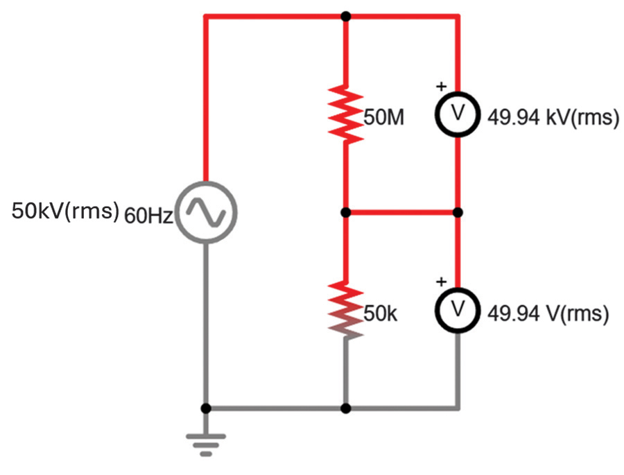
The voltage V2 across the 50-kΩ resistor is a function of the primary voltage Vp and both resistors (R1 @ 50MΩ and R2 @ 50kΩ) where:
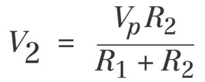
In this way, voltage sensors act like potential transformers; they step the primary voltage down to a level tolerable for protection and control devices. With the example voltage sensor, you could theoretically use a low-voltage device such as a multimeter to confirm transmission voltage.
Note that capacitors and inductors can divide voltages just as readily as resistors via capacitive and inductive reactance, respectively, provided that the source voltage is alternating and not direct. Hence, hypothetical impedances Z1 and Z2 will replace resistances R1 and R2 in an AC voltage divider containing a combination of resistances and reactances.
HAZARDS
As is so often the case in electrical engineering, circuits can act as tools or as hazards. Here are two specific hazards posed by voltage dividers that I’ve encountered in the past year as a test technician.
Ungrounded Frames
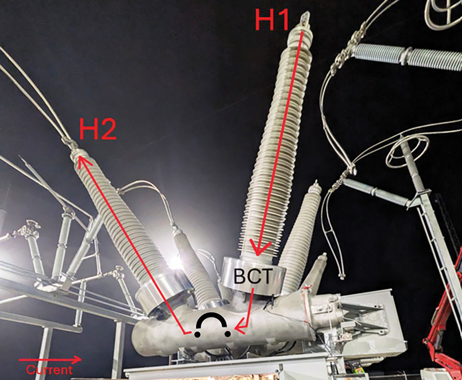
Last December, I was tasked with testing bushing current transformers (BCTs) at a large wind substation. This included testing the BCTs inside two 362-kV SF6 circuit breakers. These BCTs were hidden beneath grounded metal shrouds; the pole number was posted on them (three phases, six poles). You must connect your test set to the BCT H1 and H2 terminals to test them. This can be done by closing the breaker and then using the line and load bushing terminals for that particular phase as your H1 and H2 points (Figure 2).
This is easy on 38-kV breakers and below, but nightmarish on 362-kV breakers because of the distances your leads must travel. As an alternative to high-voltage breakers, I use the lip of the BCT metal shroud as my H1 and the breaker frame as my H2 (Figure 3a and 3b). This works because the shroud (at least on some breaker models) routes through the center BCT just like the bushing conductor and then bonds to the grounded breaker frame.
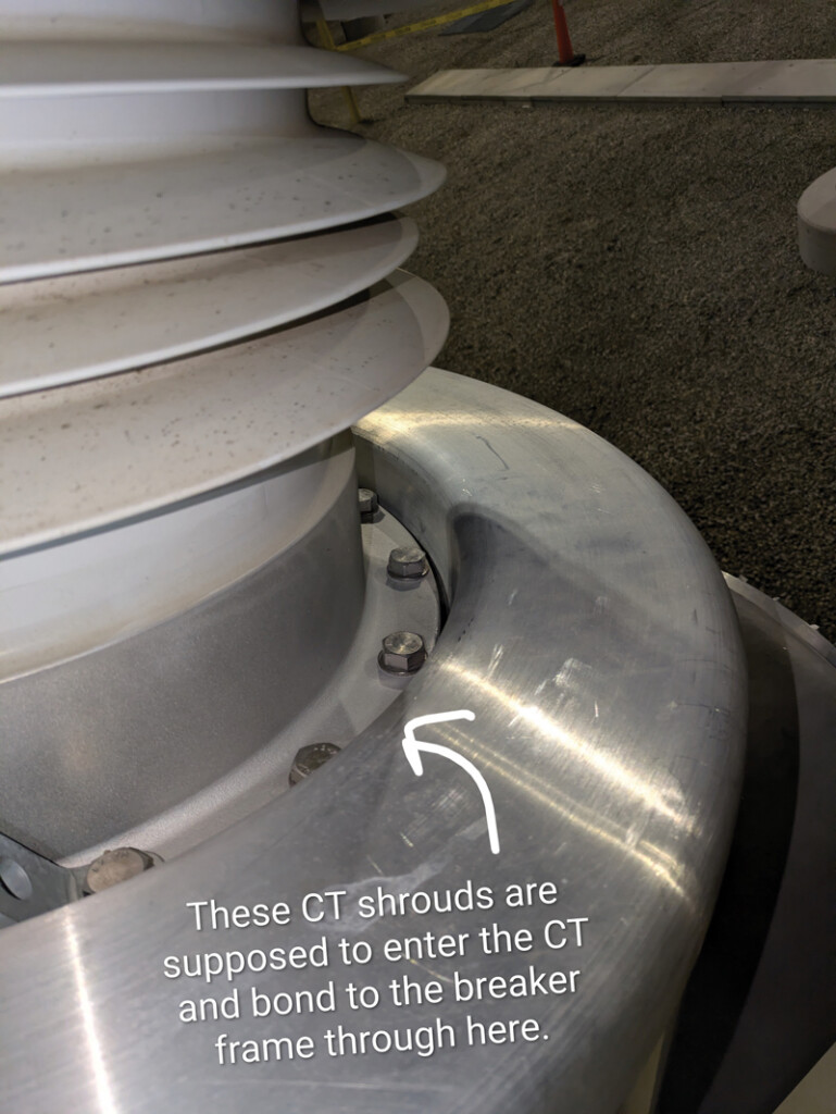
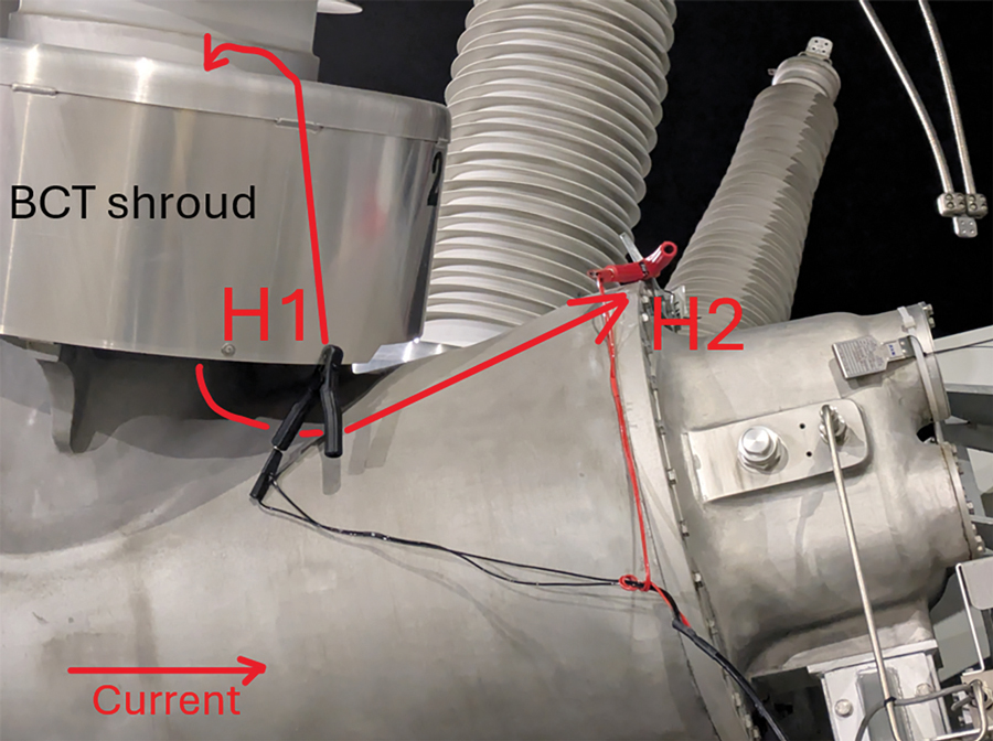
I made my connections with my CT test set but kept getting an Open CT Primary fault message, meaning there was no continuity between the H1 and H2. After more than an hour of troubleshooting (checking the test leads, replacing the test set, checking different BCTs, etc) I discovered that the culprit was the BCT shroud itself. It was, bafflingly, ungrounded, i.e., floating (Figure 4).

I still don’t understand how the shroud managed to be firmly bolted to the frame and still remain ungrounded, but my test sets didn’t lie. The hazard that arises from this comes in the form of a voltage divider.
The impedance Z1 between the bushing conductor and the metal shroud is likely to be exceedingly high—on the order of 1 TΩ. Suppose the impedance Z2 between the shroud and ground is 2.5 GΩ. There are capacitive reactances between these components as well, but their effect on the impedances will be negligible. If we plug these values into the voltage divider (200 kV is Vp, 1 TΩ is Z1, and 2.5 GΩ is Z2), then the resultant voltage V2 between the shroud and ground will be 499 V. That voltage presents a serious risk of severe injury if someone were to accidentally come into contact with the shroud while the unit is energized.
Test Set Grounding
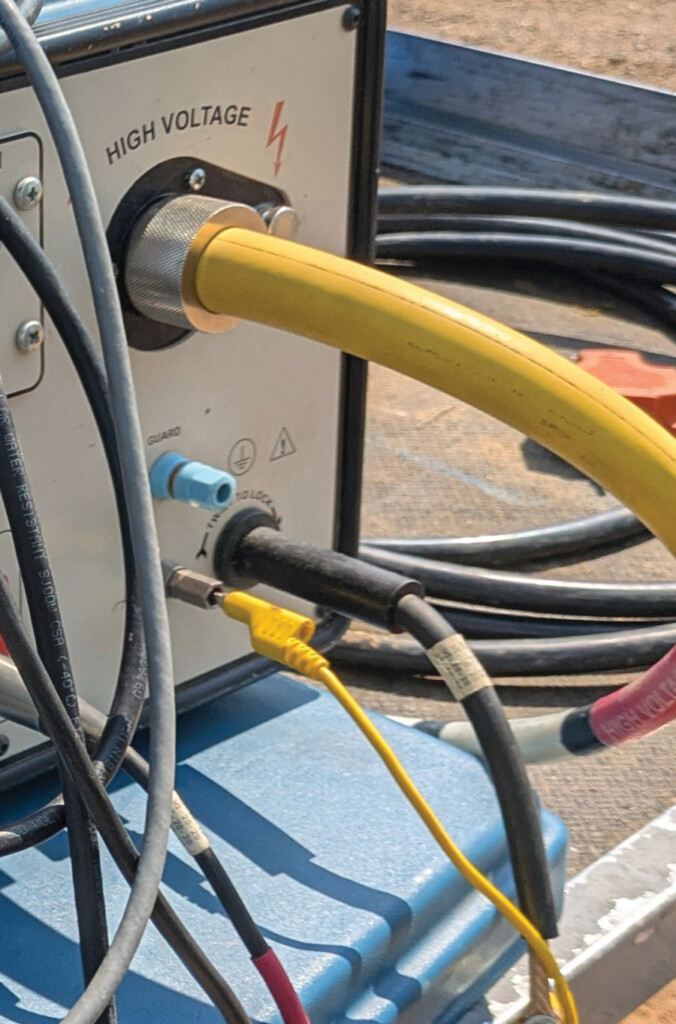
Test technicians are masters at improvising, often without thinking of the consequences or other risks they are introducing into the system under test. One example that can have deadly results is bypassing the power-factor test set ground relay. I see this most commonly on Doble M4100 test sets, but I would not be surprised if techs made similar contraptions for other test sets.
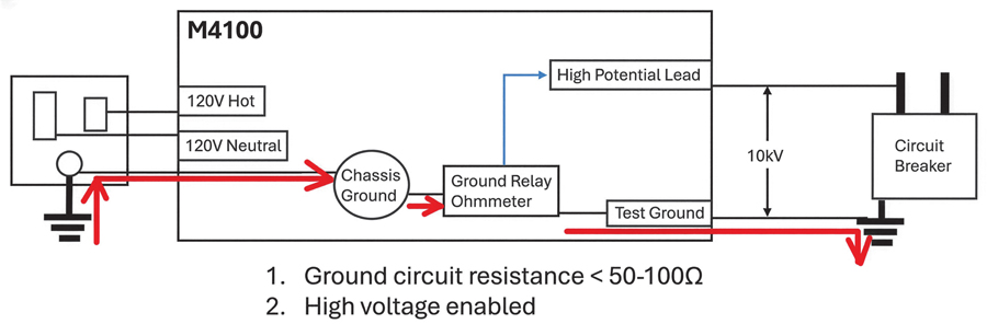
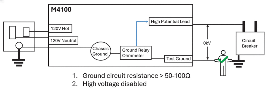
The function of the ground relay on a power factor test set is to de-energize the high-potential lead should a break in the ground relay circuit occur. That circuit includes the ground relay ohmmeter, the test ground, the asset ground, the power source ground, and the chassis ground. If the ground relay ohmmeter calculates less than 50–100 Ω between the test ground and the chassis ground, the voltage between the high-potential lead and the test ground is enabled (Figure 5). Otherwise, it disables the voltage on the high-potential test lead.
SOURCE: PRINTED WITH PERMISSION FROM RICHARD MALDONADO
SOURCE: PRINTED WITH PERMISSION FROM RICHARD MALDONADO
In the event that the test ground is inadvertently removed from the asset ground during testing, the high-potential lead’s function as a safety feature to ensure all lethal voltages are immediately terminated is deactivated.
Test technicians often find themselves on job sites where utility power is not available, so portable generators are utilized to power the test equipment. Bonding the generator to the same ground grid as the asset under test is often overlooked. By not properly bonding the generating source of power to ensure there is a complete grounding path, the ground relay circuit, by design, will disable the unit.
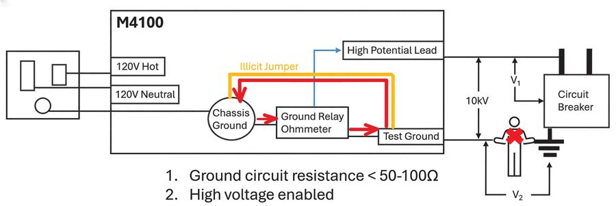
As a workaround, technicians defeat this safety feature by bonding the chassis ground directly to the test ground with an illicit jumper (Figure 7 and Figure 8). This ill-advised and dangerous practice establishes continuity between the chassis ground and the test ground, thereby satisfying the ground relay 50–100-Ω resistance condition and re-enabling the high-potential lead, but bypassing the asset ground and the power source ground.
SOURCE: PRINTED WITH PERMISSION FROM RICHARD MALDONADO
If the asset ground is inadvertently removed or overlooked during installation, the high-potential lead will remain energized because the ground relay ohmmeter was tricked into believing the grounding path was complete. A voltage divider will establish itself, where the primary voltage Vp between the high-potential lead and the test ground will remain intact (10 kV in this case). Unfortunately, it is the technician who will complete the path to ground from the specimen under test, with potentially deadly results.
CONCLUSION
Ungrounded systems allow components to float, and hazardous voltages may emerge between floating components and ground. The two hazards described here are prevented via proper grounding, by grounding all non-current-carrying conductors in a circuit breaker or creating a comprehensive ground loop with a test set.
Moreover, test set manufacturers such as Doble, Megger, and OMICRON specifically design their equipment to operate a certain way. They know more about their merchandise than you do. If you find yourself having to be creative in order to operate a piece of test equipment, it’s highly likely something is wrong with your setup, not with the unit itself.
REFERENCE
Paul Falstad. Circuit Simulator Applet. Free to use at https://www.falstad.com/circuit/.

Michael Labeit is a Prime Power Production Specialist, Lineman, a Power Systems Technician for RESA Power, and a NETA Level 3 Technician in the 249th Engineer Battalion, U.S. Army Corps of Engineers. He has operated and maintained medium-voltage power plants in Turkey and Saudi Arabia as well as at Ft. Leonard Wood, Missouri, and Ft. Bragg, North Carolina. Labeit graduated from Prime Power School in 2018 and has an AAS from Excelsior College.