

The fall of potential (FoP) test to measure the ground impedance of a data center building or substation is commonly specified as part of start-up and commissioning testing. This test procedure is spelled out in IEEE Std. 81, IEEE Guide for Measuring Earth Resistivity, Ground Impedance, and Earth Surface Potentials of a Ground System. To obtain good data,a properly executed test must meet many caveats and conditions.
Two main requisites are frequently missed or ignored:
- The facility under test must be de-energized and isolated from all external grounds, including:
a. Utility power/substation
b. Temporary power
c. Water/gas
d. Other buildings (campus) - The current return probe must be located five to 10 times the longest length (usually diagonal) of the facility under test.
Other known issues related to FoP testing include interference from other metallic buried objects, stray currents and noise, low signal-to-noise ratio, and no interpretation of the data.
Sites often believe they are isolated, but experience has led us to test continuity upon arrival. We often find that the facility is bonded to something. As it is often impossible or impractical to isolate the site, this condition means the test diagonal distance is now larger than previously planned, and the current-return probe must be located farther away based on the new diagonal.
IEEE Std. 81 also mentions a subset of the FoP test: the 62% rule. In homogeneous soil under perfect conditions, the impedance value is approximately 62% (61.8% mathematically) of the distance from the site on a graph of resistance versus distance. This has led to a shortcut in performing testing at the 62% point (and a couple of points on either side of 62%) and reporting this number as the facility’s resistance to ground. The problem with this shortcut is that most sites today cannot be isolated, are not in homogeneous soil, and are likely near a built-up environment that rules out perfect conditions for this version of a ground test.
The following examples illustrate common ground testing mistakes and challenges for data centers and their substations.
EXAMPLE 1: DATA CENTER SUBSTATION, OHIO
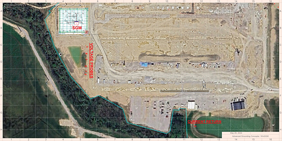
To test this site, two attempts using FoP were made. The testing personnel, who were told the site was isolated, proceeded with a standard FoP test without confirming the site’s isolation through a continuity test. In reality, the site was connected to three utility feeder lines and not isolated, invalidating the measured data in both cases.
This site was successfully tested using a computer-based multimeter as prescribed in IEEE Std. 81. This method does not require de-energization or isolation and reduces the distance required for the current return probe to twice the diagonal distance of the site under test (Figure 1).
EXAMPLE 2: DATA CENTER BUILDING, GEORGIA
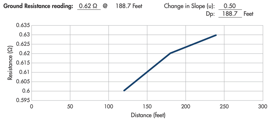
This site was first tested with the FoP method. The building has a 1,400-foot diagonal; five times that distance is 7,000 feet. The testers went 300 feet from the building and reported a reading of 186 feet (62%) as the building’s ground resistance value (Figure 2). This is an invalid test for several reasons:
- They didn’t go far enough with the current-return probe
- They relied on 62% rule–not valid at this site
- They needed to develop a complete test curve (measure every 10%)
- They didn’t confirm that the building was isolated
The site was retested with the computer-based multimeter (Figure 3) after determining that the building was bonded to the substation. The site’s grounding system diagonal now measured 2,500 feet. For a proper FoP, the current return probe had to be a minimum of 12,500 feet (almost 2.4 miles) away–not 300 feet. Using the computer-based multimeter, the distance was reduced to 5,000 feet, which was still a bit of a hike.
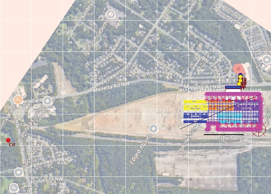
Note: Even using a computer-based multimeter, testing errors and bad data are still possible if you fail to go far enough away from the site under test. Always confirm the site’s isolation and diagonal before testing, regardless of the chosen test method.
EXAMPLE 3: DATA CENTER BUILDING, GEORGIA
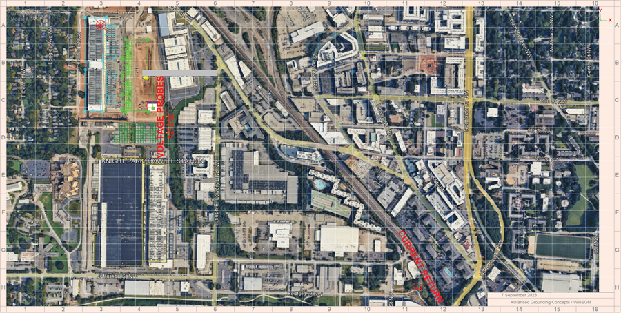
This new data center building on a campus was tested with the computer-based multimeter. The building was allegedly isolated, but we successfully conducted a test and obtained good data (Figure 4).
KEY TAKEAWAYS
The FoP test is still specified as part of start-up and commissioning testing for many sites. You must understand the requirements of this test to determine whether the FoP test method can be successfully performed. The criteria include:
- De-energization and isolation must be confirmed on site with a continuity test.
- Locate the current-return probe a minimum of five times the diagonal distance of the site. The larger the site, the farther you must go—up to 10 times the diagonal distance at very large sites.
- Measure every 10% of the distance to develop a full test graph to find the true resistance value. Testing at 62% will rarely be successful, especially at a large site like a data center.
CONCLUSION
If these conditions can’t be met, an alternative test method, such as using a computer-based multimeter, is required for a successful test. Whatever the test method, testing personnel need extensive experience in grounding testing, substantive knowledge of IEEE Std. 81, and appropriate test equipment and training to perform a proper test and obtain valid data.

Lee Howard is a senior grounding specialist with Hood Patterson & Dewar, Inc. With more than 25 years of experience, Howard specializes in the design and analysis of grounding, lightning protection, and surge suppression systems. He speaks at various industry conferences and offers grounding testing and consulting services to a wide range of domestic and international clients, including electrical utility, industrial, and commercial sites. Howard holds two patents in grounding and lightning protection products. He earned a BS in electronics engineering technology at DeVry University and a Power Systems Certificate from the Georgia Institute of Technology.

Jacob Rioux is a Grounding Specialist at Hood Patterson & Dewar, Inc. With a background in substation design and testing, Rioux provides substation and facility grounding system testing and safety analysis. He also performs soil resistivity testing and grounding system design for new construction. His client base includes electric utilities and industrial and commercial facilities. He provides grounding articles, training, and presentations for conferences and clients nationwide. Rioux has a BS in mechanical engineering technology with a minor in electrical engineering technology from the University of Maine.