

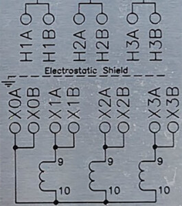
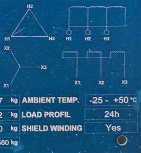
If you’ve worked on transformers in renewable energy circuits, as I have for the past six months, you’ve likely seen many—perhaps most—equipped with electrostatic shields, grounded copper or aluminum sheets wedged between the high- and low-side windings. The existence of these shields inside transformers is normally (but not always) readily identifiable via the unit data plates (Figure 1). Some affirm the presence of a shield with a grounded, dotted line running between the windings; others label the dotted line with “Electrostatic Shield” or “ESS”; others indicate the shield with a simple “Yes.”

These shields are designed to protect loads from overvoltage transients that are common in renewable circuits. While these features may enhance the integrity of renewable circuits, they sow confusion among test technicians due to their unique effect on power factor test results.
LOW CHL CAPACITANCE
As Khanali and Jayaram (2015) state, “The main functionality of the electrostatic ground shield is to capacitively decouple the primary and secondary windings. The advantage of this method is suppressing the transfer of high-frequency contents of voltage generated on each side of the transformer to the other side.”
This works, they say, because “the electrostatic shield basically acts as a capacitive filter to prevent the transfer of critical voltage components onto the secondary side.” This capacitive decoupling manifests itself as (much) lower high-side to low-side (CHL) capacitance compared to that of unshielded transformers.
Table 1 represents power factor test results recently gathered on a 4,200-kVA, 35.4-kV/480-V delta-wye, shielded Hitachi transformer. Observe the exceedingly low capacitance of the CHL insulation.

LOW CHL CURRENT AND WATTS LOSS
The difference between the grounded specimen test (GST), the grounded specimen test with guard (GST-G), and the ungrounded specimen test (UST) is the current the test set is measuring.
- The GST applies a voltage across CHL and CH, then measures the current through both CHL and CH.
- The GST-G applies the same voltage across both insulators, but measures only the current through CH.
- The UST applies the same voltages, but measures only the current through CHL.
All current wants to return to its source. The electrostatic shield provides a low-impedance path for current flowing in either winding to return to the source via ground, instead of to the other winding (Figure 2). As a result, when voltage is applied between the high and low sides during testing, current that would normally flow through CHL (as measured by the UST ammeter) flows instead through ground (as measured by the GST-G ammeter) through the high side to ground insulation (CH) and the high side to shield insulation (CHS).

Some current still flows from the high side to the low side, but it is minimal. This explains the low CHL current measurements in Table 1.
It also explains the low CHL watts losses because the insulation watts loss W is the product of the test voltage VT, the total current measured IT, and the power factor PF, or W = VT(IT)(PF). As total current IT decreases, so must watts losses W.
NEGATIVE POWER FACTOR
Power factor is a function of cosine (θ). Angle θ is the angle between the test voltage VT (or the resistive current Ir) and the total current IT (Figure 4). For a power factor to be negative, the angle between the applied voltage and total current would have to be above 90 degrees and below 270 degrees. For example, if angle θ equals 120 degrees, then the power factor equals cosine (120 degrees°) equals -0.5.

Negative power factors are impossible. Real power cannot exceed apparent power; resistive current cannot exceed total current. Negative power factor measurements, however, are a well-documented phenomenon.
A common cause of negative power factor measurements is an unknown path for resistive current back to the source, typically via ground. How this is possible can be explained as follows. Suppose a technician performs a power factor test on an asset as illustrated in Figure 4.
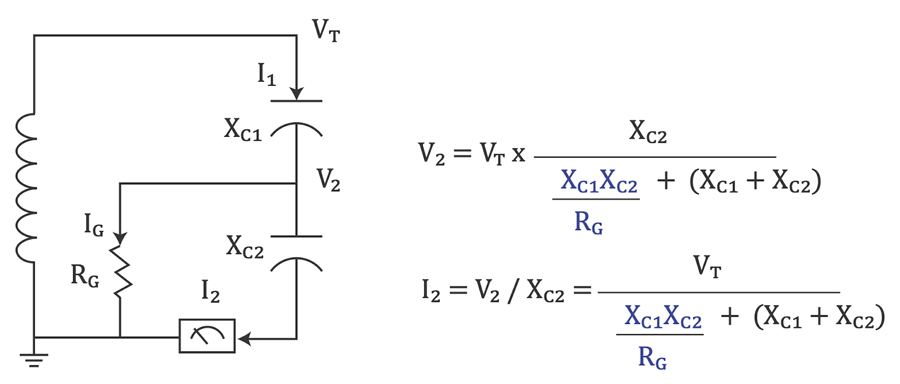
The technician may think that the asset is composed simply of one capacitive layer, but suppose a surreptitious path RG for resistive current IGback to the source exists somewhere in the middle of the asset. Such a path would split the single capacitive layer of the asset into two distinct, capacitively reactive layers, XC1 and XC2. The power factor test set calculates the power factor by measuring the phase angle between the test voltage VT and the current that enters its ammeter, I2.
But if the current that is supposed to enter the ammeter instead bypasses the ammeter on its way back to the test set, that current being IG, the test set will erroneously calculate the power factor. The test set sees the true test voltage, but it does not see the true total current, I2 + IG, otherwise known as I1. It only sees I2.
Let’s use some numbers. Suppose VT is 100V, XC1 and XC2 = 100Ω, and RG = 1000Ω. In that case, the current I2 that flows through the test set ammeter using the equation in Figure 5 will be:

This value of I2 converts to 0.499A ∠ 92.86° when switching from rectangular to polar coordinates. The test set sees this amperage, concludes that angle θ equals 92.86°, and calculates the power factor as cosine (92.86°) equals -0.0499. Behold, negative power factor!
The key in this erroneous calculation is the ammeter placement. If the ammeter was between the test set and the ground connection, it would intercept all current I1, including resistive current IG, and the power factor calculation would instead be:

This value simplifies to a power factor of 0.0497.
In the case of a shielded transformer, XC1 + XC2 represents the capacitive reactance of CHL, and RG represents the electrostatic shield acting as a path back to the source that splits CHL into two capacitances. Because the shield redirects the vast majority of the current from the UST ammeter to the GST-G ammeter during power factor tests, USTs tend to render small or even negative values for CHL, as is evidenced by Table 1. Pong (2002) has a highly recommended and masterful discussion on this topic.
WHAT TO DO?
Power factor measurements from USTs on shielded transformers are of limited value, though, as Pong (2002) indicates, they can reflect changing conditions of the shield ground connection. Capacitance measurements from USTs remain sound examples of trendable parameters; their changes over time are worth noting. The same applies to GST-G tests of CH and CL power factors and capacitances; these remain valid as well.
REFERENCES
- Khanali, M., & Jayaram, S. H. (2015). “Effectiveness of Electrostatic Shielding in Suppressing the Impact of Fast Transients on Transformer Insulation,” IEEE Conference Publication | IEEE Xplore. Retrieved from https://ieeexplore.ieee.org/document/7352146/.
- Labeit, M. D. (2024). “Keeping Machines Dry,” NETA World, Fall 2024. Retrieved from www.netaworldjournal.org/2024/08/michaellabeit/columns/keeping-machines-dry/.
- Pong, L. (2002). Review of Negative Power Factor Test Results and Case Study Analysis,” 70th International Conference of Doble Clients, Boston, Massachusetts, USA.

Michael Labeit is a Prime Power Production Specialist, Lineman, a Power Systems Technician for RESA Power, and a NETA Level 3 Technician in the 249th Engineer Battalion, U.S. Army Corps of Engineers. He has operated and maintained medium-voltage power plants in Turkey and Saudi Arabia as well as at Ft. Leonard Wood, Missouri, and Ft. Bragg, North Carolina. Labeit graduated from Prime Power School in 2018 and has an AAS from Excelsior College.