
It is often observed that discontinuities exist between factory acceptance and field commissioning tests of power transformers. Ideally, the two test sessions are well-coordinated, allowing measurements captured at the transformer manufacturer to be easily replicated once the transformer is prepared for service.
No two transformers are identical, and if segments of a transformer’s history are unavailable, those responsible cannot make the most informed decisions. In some instances, baseline factory tests are not repeatable. This article discusses observations of the gaps between these two test sessions and provides recommendations to improve the communication of expectations and results throughout this process. It is intended for technicians, engineers, procurement personnel, and asset managers involved in developing transformer purchasing specifications, factory acceptance testing, field commissioning testing, and final acceptance of the transformer.
WHY DO WE PERFORM OFF-LINE ELECTRICAL TESTS?
An incredible amount of time, energy, and resources is devoted to performing and analyzing off-line electrical tests of power apparatus. While it is easy to discount these tests as one box checked in the process of commissioning or maintaining an expensive piece of critical infrastructure, the reality is much more comprehensive.
Electrical apparatus—specifically transformers and bushings—can be considered living beings that age and deteriorate over time, each with unique life experiences. Properly analyzing off-line electrical testing is not accomplished solely through software algorithms and numerical calculations. Assessing condition based on the equipment’s responses to electrical interrogation is a skill that requires experience and familiarity with the failure mechanisms that end (or shorten) an asset’s life.
Electrical testing is a reliable means of assessing the condition of a transformer’s insulation system, electromagnetic circuit, and physical properties. Within a relatively short time, the health of these integral structures can be evaluated by applying electrical stresses with portable equipment. Experience has demonstrated that if a transformer’s response to an electrical interrogation shows a change, failure or deterioration mechanisms can often be predicted. Depending on the nature of the issue, remedial options may be available. Interpreting these changes allows for proactive intervention—an ideal opportunity in an environment of increasing transformer criticality.
WHAT EXPERIENCES DID A TRANSFORMER HAVE AT THE BEGINNING OF ITS LIFE?
Design and Construction
In transformer factories, raw materials are manipulated and constructed, pursuant to an engineered design, to form a highly efficient apparatus. Material or design insufficiencies can plague a transformer’s reliable operation. Performing factory acceptance testing challenges the design, materials, and construction, ideally identifying defects before the transformer leaves the factory.
Factory Acceptance Testing
Factory-performed tests of transformers and bushings are driven by industry standards such as IEEE and IEC, as well as company purchasing specifications. A significant effort is focused on developing and enhancing these requirements based on experience and technology improvement. The combination of industry standards and purchasing specifications ideally results in the delivery of not only a reliable asset, but also a collection of records that future test results may be compared against.
For distribution- and power-class transformers built in accordance with IEEE Std. C57.12.00, the manufacturer should provide certified test reports to the purchaser, and many purchasers condition the shipment of the transformer on the approval of the transformer’s certified test report. This report gives the purchaser an opportunity to identify any concerns with the test records and request remedial action, if warranted. While all transformers should be manufactured with the same attention to detail, the additional tollgate of test-report approval necessitates that the manufacturer properly audit the test records.
WHAT IF THE REQUIRED FACTORY TESTS FAIL TO DEMONSTRATE THAT REPAIRS WILL RESULT IN A RELIABLE TRANSFORMER?
There are instances where the minimum factory acceptance test requirements cannot detect specific defects. With small distribution transformers built according to IEEE Std. C57.12.00, insulation resistance, insulation power factor and capacitance, and dissolved gas analysis are not required unless specified. Only Class II power transformers require routine partial discharge testing, one of the best indications of insulation quality. Regardless of the transformer class, some defects might go undetected during factory acceptance tests. True transformer defects will later be identified through the electrical acceptance or maintenance tests, dissolved gas analysis, initiation of the transformer protection scheme, or eventual failure.
WHAT IF THE TRANSFORMER FAILS THE FACTORY ACCEPTANCE TEST?
While failing to pass a factory acceptance test is not an ideal situation, the objective of performing these tests is to identify an unacceptable condition. It is not a far reach to understand that high demand, supply-chain constraints, and skilled-labor shortages do not align with quality objectives. When a transformer fails a factory acceptance test, some level of investigation and repair/replacement activity is undertaken to remediate the condition before repeating the tests. Minor defects, such as a loose connection, an inoperable de-energized tap changer, or a conductor’s clearance to ground might be easily repaired without removing the core and coil assembly from the tank. In severe cases, winding or construction defects may require removing the core and coil assembly from the tank for investigation, repair, or replacement. Best practice is to involve the transformer purchaser and their subject matter experts, in this process to ensure that appropriate repairs are made and an acceptable retest plan is prescribed.
Preparation for Shipment
The steps in preparing a transformer for shipment depend largely on its dimensions, weight, transportation permitting restrictions, and purchasing specifications. A distribution transformer may be cleaned and packaged for local transportation after completing the factory acceptance tests without requiring significant attention. On the other hand, transporting a large power transformer to its destination may require the removal of its insulating liquid and partial disassembly. In some cases, transitioning high-voltage autotransformers and/or transformers with buried delta windings to operational condition may require internal modifications.
Transportation
The opportunity for damage increases as the number of transportation modes increases. While smaller shipments from local manufacturers may require brief highway transportation, large power transformers may require a notoriously rugged ride on a railcar. In North America, a significant number of transformers are purchased from international manufacturers, requiring cross-ocean shipment in addition to rail and/or road transportation. Each transportation mode and each transition between transportation modes incurs additional risk to the transformer’s condition.
Critical damage can result from shipments hitting bridges, hard railcar humping, and rough placement onto the transformer’s foundation. Any breach of the transformer’s internal atmosphere introduces an opportunity for insulation to be compromised. Impact recorders, visual inspection, and electrical test comparisons are critical in evaluating the quality of the transformer’s journey.
On-Site Assembly
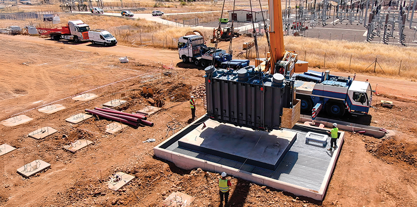
Once the transformer is placed onto its permanent or temporary foundation, assembly efforts are often required to bring it into operational condition. Locations that do not involve environmental considerations are rare, as most transformers requiring assembly are located outdoors, exposed to the whims of Mother Nature.
Significant exposure to a humid atmosphere, improper control of foreign material (i.e., tools and hardware), and negligent behaviors during confined-space entry may introduce opportunities to compromise the insulation. Parts might not have shipped with the transformer, and if they are available, they may not fit, leaving those tasked with assembly without access to the drawings and documentation necessary for the design’s intended assembly. In an ideal world, all transformer components are fully assembled before final field assembly. Any field fabrication efforts or poorly guided attempts at assembly can risk the transformer’s reliability.
FIELD ACCEPTANCE TESTING A NEW, FULLY ASSEMBLED TRANSFORMER
The technician or engineer who receives a new transformer in the field may not be aware of its history. The certified test report and native (electronic) test files may not be accessible or may have been communicated only to another department within the purchaser’s organization. The engineering team responsible for new equipment purchases may not have a robust interface with those tasked with operating and maintaining the transformer. If the technician or engineer is performing contract work for an asset owner, yet another layer of abstraction may conceal the transformer’s history.
In the realm of field acceptance testing, strange electrical test results may be encountered, especially for new installations, when testing during a transportation interval, or when grounding systems are not yet in place. New substations or industrial facilities may accept new transformers without the supporting infrastructure in place. These challenging situations are often managed on an individual basis by establishing a reference ground.
In many instances, unexpected test results are representative of the transformer, but hours may be spent establishing appropriate ground references, mitigating environmental conditions, and verifying that the test instrumentation is operating properly.
Herein lies an opportunity for improvement. The transformer’s baseline results may not be accessible to the individual tasked with interrogating its acceptability at its final destination, if the baseline results even exist.
If baseline results are available, were the conditions in which the results were obtained properly documented, and can they be replicated in the field? Several frequently encountered factors result in differences between field acceptance and factory acceptance test results:
- Tap changer positions and switches/link-boards used for modifying dual-voltage or vector relationships can introduce differences when comparing many of the typical electrical tests.
- The presence, absence, or difference of insulating fluids between the two test sessions can introduce discrepancies. As of this publication, the IEEE standards do not require testing a transformer with the operating fluid it is designed for, and variations in the permittivity of the insulating fluid can introduce differences in the capacitive behavior of an insulation system, thereby influencing the electrical test results.
- For example, a KNAN-rated transformer designed for use with natural ester fluid may be tested in the factory with mineral oil because handling and storing natural ester fluid can be a challenge to efficient factory throughput. Additional equipment, labor, and cost may be required to perform factory acceptance testing with an alternative fluid.
- In another example, a shipping-condition sweep frequency response analysis (SFRA) test is required before and after transporting the transformer from the factory to its foundation. However, the manufacturer may have performed the shipping SFRA test when the transformer was filled with mineral oil, while the post-transport test may be performed while the transformer tank is filled with dry air.
- Bushings are an inherent contributor to a transformer’s insulation system, and they play a role in the electrical test results. In some situations, the transformer in the field may have different bushings than those used for factory acceptance tests. Some examples include:
- The original bushings were damaged during preparation for shipment at the factory or during transportation.
- The original bushings were kept at the factory for performing factory acceptance tests of a sibling transformer for the same asset owner.
- The original bushings were subjected to a service advisory and required replacement.
- The magnetic state of the transformer core is often a source of unexpected test results or changes from benchmark results. Testing a transformer’s electromagnetic circuit may be impacted by the core’s magnetic state. Factors influencing the magnetic state of the core include:
- Prior DC winding resistance measurements without a subsequent attempt at demagnetizing the core
- Inadequate demagnetization
- Overvoltage conditions/saturation of the core
- Switching operations
- The connections associated with deltawindings may be the source of discrepancy when comparing field and factory test results. Delta windings are often incorporated as stabilizing windings that are not loaded externally but are present (buried) for harmonic suppression. The delta winding may be configured depending on the transformer’s stage of life:
- The delta winding is closed, and all three corners of the delta are made accessible for factory acceptance testing.
- The delta winding is closed and grounded internally to the transformer (externally inaccessible).
- The delta winding is closed, and one corner is made accessible through one bushing. This corner could be grounded or ungrounded during any of the electrical tests.
- The delta winding is open, and one corner is made accessible through two bushings.
- The delta may be closed by connecting the two external bushings.
- The delta may be open or closed during any of the electrical tests.
- The delta corner may be referenced to ground or left floating during the electrical tests.
FREQUENTLY USED ELECTRICAL TESTS SUSCEPTIBLE TO INFLUENCE
Turns Ratio and Phase Relationship
The turns ratio and vector relationship are a result of the transformer’s winding connections and tap changer positions. Minor influences due to the opening or closing of a delta-connected winding may be observed. Differences in the insulating fluid and bushings are not expected to cause differences in the turns ratio and phase relationship test results.
DC Winding Resistance
Tap changer positions and winding configurations will, in most cases, influence the measured resistance as turns are removed or added to the current-carrying circuit. In some cases, designs incorporate isolated series transformers (boosters) where the DC winding resistance measurements will not be affected by changes to the on-load tap changer position. These cases are easily identifiable by reviewing the transformer nameplate.
While the presence and configuration of a delta stabilizing winding may affect the process of obtaining measurements, the DC winding resistance measurements of a given winding should not be affected in most cases. Differences in bushings, provided there are secure connections between the winding and the bushing, are not expected to influence the DC winding resistance measurements.
Overall Power Factor and Capacitance
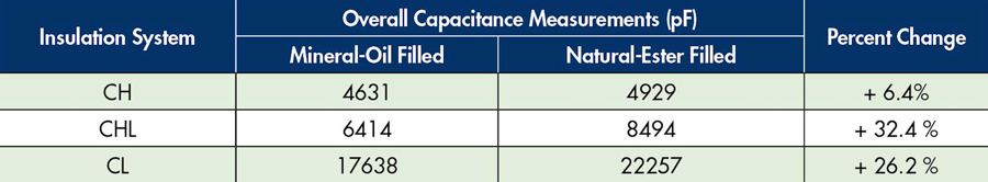
Changes to the insulating fluid of a transformer will result in a change in the overall capacitance. For example, a transformer tested with mineral oil will inherently have higher capacitance than a transformer filled with dry air. Note that overall tests performed in the absence of its intended insulating liquid should be tested at a reduced voltage to prevent insulation damage.
For example, consider the overall capacitance measurements of the two-winding, 230-kV to 13.8-kV YNyn, 100-MVA transformer shown in Table 1. This transformer was filled with mineral oil in the factory and with natural ester fluid in the field. The increase in the insulating liquid’s permittivity will cause the overall capacitance to increase. The magnitude of the increase will vary for each insulation system, depending on the volume of contributing insulating liquid.
Tap changer, dual-voltage, or vector-relationship connections can result in differences of overall capacitance, depending on the design of the transformer.
If the transformer is assembled with bushings that have a significantly different C1 capacitance than those used during factory acceptance tests, those differences will contribute to changes in the overall insulation capacitance referenced to ground potential.
The test setup of the transformer that has a delta winding that is unloaded in operation is very important. Transformers that have a loaded delta tertiary winding (with all three corners accessible) should be tested as a three-winding transformer; this approach results in six unique insulation systems.
In a transformer with only one corner of the delta tertiary accessible, inconsistency in test practices has been observed. The transformer is ideally tested as a three-winding transformer; however, it could be tested as a two-winding transformer if the delta tertiary is grounded during the test. Variations in these configurations will result in different overall capacitance measurements.
Single-Phase Exciting Current and Loss
Tap changer positions will play a role in the behavior of the exciting current and losses under single-phase excitation. Changes to the energized winding’s number of effective turns will change the magnetic flux, thereby changing the exciting current and losses. The tap position of lower-voltage windings (i.e., an on-load tap changer on the LV winding) may cause intentional loads during this open-circuit test, resulting in a change to the measured exciting current and losses. Such intentional loads include preventive autotransformers used with reactive-type on-load tap changers and/or series transformers.
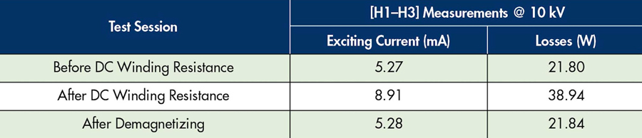
As demonstrated in Table 2, the effects of residual magnetism are commonly observed during the single-phase exciting current and loss measurements. Efforts to demagnetize the transformer core are often successful at reducing the impact of the core’s magnetic state. Notably, the core’s magnetic state is constantly changing, even without external influence, due to the effects of magnetic viscosity.
The presence and connections of a delta stabilizing winding may influence the behavior of the exciting current and losses, notably the capacitive component of the exciting current. For this reason, extracting the exciting current components and evaluating the purely resistive watts measurement is encouraged.
While differences in insulating liquid (i.e., mineral oil vs. natural ester) are not expected to produce any observable differences in the exciting current and loss results, caution should be observed if attempting to perform single-phase exciting current and loss tests when the transformer is empty.
Leakage Reactance and Loss
The leakage reactance results are dependent on the tap changer positions of the transformer. The impedance of the transformer changes as the tap changer positions change, influencing the reactance measurement. Neither the presence nor the absence of insulating fluid, differences in bushings, nor the presence or configuration of a stabilizing tertiary winding are expected to change the measured leakage reactance.
While the first iteration of low-voltage leakage reactance measurements is often compared against the factory-measured impedance measurements, it must be recognized that differences in flux distribution exist. For a three-phase transformer, the factory impedance measurements are made using a three-phase power source, whereas the field measurements are most often made using a single-phase source. Note that per-phase measurements are preferable, if feasible, because the reactance measurements of the individual phases can be compared to further investigate winding deformation.
Sweep Frequency Response Analysis
Sweep frequency response analysis (SFRA) may be the most sensitive test to all the aforementioned factors because it interrogates both the inductive and capacitive nature of the transformer. Changes to the frequency response in the lowest frequency region are often encountered due to differences in the magnetic state of the core; however, significant changes may be indicative of an issue within the transformer’s electromagnetic circuit. Like the aforementioned tests, differences in tap changer positions, delta winding configurations, and connected bushings contribute to differences in the frequency response of the transformer under test.
As described with overall capacitance measurements, differences in the permittivity of the insulating fluid will cause a change to the capacitive behavior of the transformer, resulting in a shift of the resonance frequencies of the transformer’s frequency responses. Expectations are more easily established if the condition of the transformer under test is well-detailed in the test records.
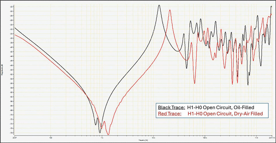
Figure 1 demonstrates a situation where the manufacturer performed a shipping-condition SFRA, but with the tank filled with mineral oil. After the transformer was received in the field, SFRA measurements were repeated with the transformer tank drained. Changes to the frequency response, particularly the resonance frequencies, are expected for this difference in insulating medium. Because air has a relative permittivity lower than mineral oil, the frequency response is expected to shift towards higher frequencies.
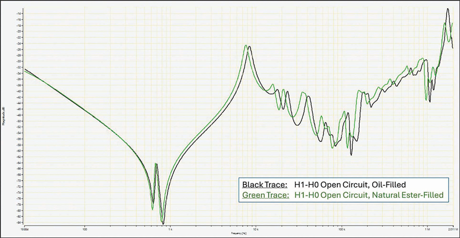
In Figure 2, the SFRA tests were made on the same transformer while the core and coil assembly was immersed in different insulating liquids. Knowing the difference in insulating liquid sets an expectation of frequency response shift. For example, because the relative permittivity of natural ester is higher than that of mineral oil, it is expected that the trace shifts toward lower frequencies. If this situation was not documented in the test records, suspicions of physical change may be justified.
RECOMMENDATIONS
When considering the sources of discrepancies during electrical tests, how might these challenges be alleviated? Our objective is to assess the health of the transformer, and we are aided by being able to replicate the exact configurations in which baseline results were established.
The following recommendations are provided to ensure efficiency in the process of assessing a transformer’s condition in the field as compared to its factory benchmarks.
- If an asset owner’s transformer acceptance and maintenance testing protocol includes electrical tests exceeding minimum industry standards, request that these tests be performed at the factory to establish reliable benchmarks to which future results may be compared. IEEE standards for new power and distribution transformers do not require tests such as leakage reactance and sweep frequency response analysis.
Measurements of exciting current and losses are generally performed in nominal tap changer positions, unless otherwise specified; however, many field test plans include tests in at least half of the on-load tap changer tap positions. Purchasing specifications that require the transformer to be factory-tested with its intended fluid of operation may be warranted. - Factory test specifications for tests also performed in the field should be explicit and, if necessary, should prompt further discussion between the purchaser and manufacturer. If an asset owner’s maintenance testing protocol requires a test to be performed in a specific manner, the best time to establish expectations of future behavior is while the transformer is undergoing factory acceptance tests. Requesting a test by name, without identifying the specific tap changer and configuration requirements, may not provide the expected records. It is of critical importance that the tap positions and all pertinent connections and configurations are noted.
Ideally, electronic test records are provided to reduce administrative work during field acceptance testing. Evaluating and comparing tests, such as SFRA, by reviewing paper or PDF reports is challenging, and defects may go undetected when analyzing flattened or paper records. Tools incorporated in many testing software packages assist in comparing test records. - Develop communication to ensure that operations and maintenance personnel have access to the factory results and history of incoming transformers.
Factory test reports, factory failure reports, and electronic test records are ideally made available to the appropriate parties. Not only does this history provide a full perspective of the transformer’s infancy, but it also provides clues as to what issues could be experienced during the remaining decades of the transformer’s life.
CONCLUSION
Numerous risks challenge the successful creation, delivery, and commissioning of new transformers. The objective of the factory and field commissioning tests is to ensure that the transformer will operate reliably and that there have been no unintended changes throughout its early life. Test records developed at the transformer manufacturer are preferred benchmarks against which future test sessions are compared. These records should be properly detailed and made available to the teams tasked with receiving and evaluating the transformer at its final destination. The reliability of critical infrastructure is best served by the sharing of information and informed decision-making.
REFERENCES
- IEEE C57.12.00-2021, IEEE Standard for General Requirements for Liquid-Immersed Distribution, Power, and Regulating Transformers.
- Lachman, M.F. “Frequency Response Analysis of Transformers and Influence of Magnetic Viscosity,” Proceedings of the Seventy-Seventh Annual International Doble Conference of Doble Clients, 2010, Doble Engineering Company.
- Lachman, M.F. “Selected Issues of Voltage Ratio Measurement on Power Transformers, Part IV: Influence of Delta Winding,” Proceedings of the Ninety-First Annual International Conference of Doble Clients, 2024, Doble Engineering Company.

John J. Foschia has been a Principal Client Service Engineer at Doble Engineering since 2021, following eight years with SPX Transformer Solutions, where he most recently served as Product Test Manager. His experience includes factory acceptance testing and quality control of power transformers in addition to diagnostic testing and condition assessment of high-voltage electrical apparatus. Foschia is currently an Assistant Secretary for the Doble Transformers Committee and has participated in several IEEE Transformer Committee working groups. He received BS degrees in electrical engineering and computer engineering from North Carolina State University.