

Stator ground faults are one of the most common disturbances for high-impedance grounded generators. A resistor is connected across the secondary of a single-phase distribution transformer connected from the machine neutral to ground to insert the high-impedance ground. The purpose of the high-impedance ground (Figure 1) is to limit the magnitude of single line-to-ground fault current flowing in the stator windings.

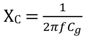
Voltage-based protection, such as measuring the voltage drop across the neutral grounding resistor (RN), is used for stator ground fault protection since the ground current magnitude in the stator is very low (e.g., 5 amps primary or less). Equation 1 calculates the distributed capacitive reactance.
Great care should be exercised when selecting the ohmic value, especially depending on the type of stator ground fault protection selected, such as subharmonic voltage injection (64S). This article illustrates such an example. Figure 2 is the single-line diagram for applying such protection.
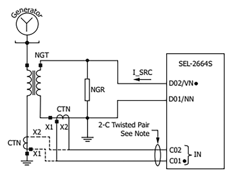
Subharmonic voltage injection (64S) is unique because it uses a current measurement to detect stator ground faults, is very reliable, and can protect the entire winding.
Equation 2 is used to calculate the size (in Ohms) for RN. Nt is the turns ratio of the grounding transformer. It is crucial to note that it determines the minimum required value, which is often not a good choice for the neutral resistor when applying 64S protection

EXAMPLE
This example shows how to calculate the minimum value for RN. The purpose of RN is to limit overvoltage so that it will not damage the generator insulation.
Power System Parameters
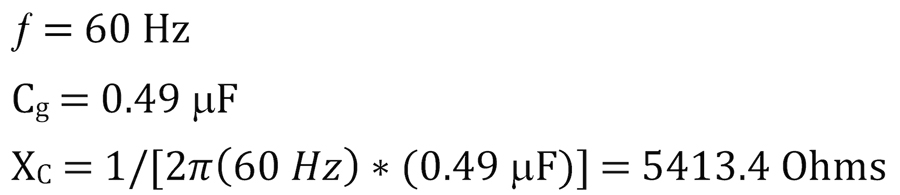
Grounding Transformer Turns Ratio

Neutral Grounding Resistor

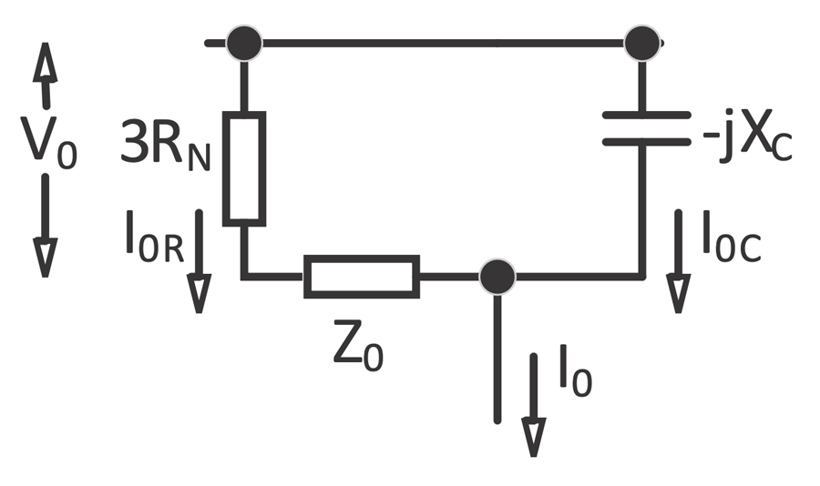
The 60 Hz component neutral current flowing on the secondary side of the grounding bank (Figure 3) is calculated as follows for a ground located at the generator terminals:
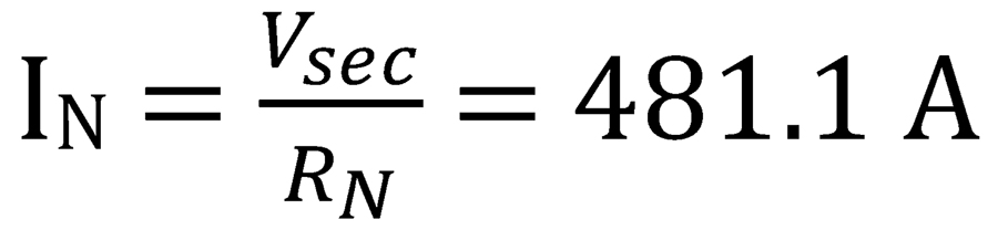
This large neutral current flows into the generator relay neutral current input (IN) and can swamp the input circuitry. A 5.0 Ohm resistor would limit the secondary current to 48 amps.
CONCLUSION
This example illustrates that using the minimum required value of resistance can have a negative impact on the overall performance of 64S protection. Some European manufacturers are aware of this condition and state how to properly size RN in their literature.

Steve Turner is a Consultant at Sargent & Lundy. He was previously in charge of system protection for the Fossil Generation Department at Arizona Public Service Company for five years. Turner formerly held positions at Beckwith Electric Company, GEC Alstom, SEL, and Duke Energy, where he developed the first patent for double-ended fault location on overhead high-voltage transmission lines and was in charge of maintenance standards in the transmission department for protective relaying. He has BSEE and MSEE degrees from Virginia Tech University. Turner is an IEEE Senior Member and a member of the IEEE PSRC and has presented at numerous conferences.