

As testers, where should we start? The standards! For grounding testing, the industry reference is IEEE Std. 81, Guide for Measuring Earth Resistivity, Ground Impedance, and Earth Surface Potentials of a Grounding System. As with most standards, familiarity and interpretation are key.
It can be a challenge to understand the intent, methods, and implementation of the prescribed testing. Fall of Potential (FOP) testing is a commonly specified test method to (attempt to) measure the impedance to earth of the ground grid under consideration. Unfortunately, we have found that many testing firms perform this test incorrectly, thus obtaining invalid results. As the test results are frequently used for ground grid commissioning, it is imperative to acquire valid data. We will present case studies and test reports that show common testing mistakes and recommend how to correct these testing pitfalls to create a successful outcome.
The concept of remote earth is integral to successful FOP testing. Per IEEE Std. 81, remote earth is defined as:
A theoretical concept that refers to a zero impedance placed at an infinite distance away from the ground under test. In practice, remote earth is approached when the mutual resistance between the ground under test and the test electrode becomes negligible. Remote earth is normally considered to be at zero potential.
Successful FOP testing requires many conditions that are frequently unmet or ignored in testing:
- Isolated ground grid. No connection to power, water, telecom, etc.
- Must perform due diligence and testing to verify if the site is isolated. Many sites believe they are isolated, but they may be bonded through construction power or other forgotten connections.
- Simple site geometry. Invalid for large, complex, or interconnected ground grids due to long lead lengths that would be required.
- Long leads act as an antenna. EMI and RFI noise may interfere with the test signal. The signal-to-noise ratio must be considered with conventional, low-power test meters.
- Homogeneous soil. Very rare
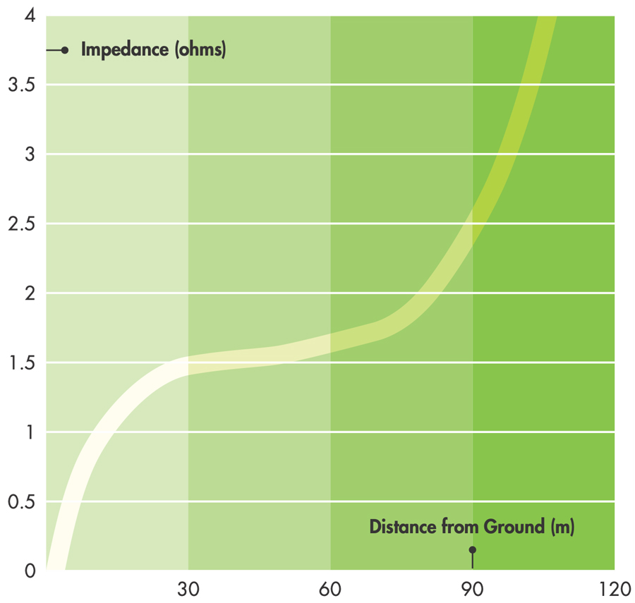
The FOP method is the most commonly specified ground-grid test method. It was developed in the 1930s, when the United States was less developed. Proper setup includes locating the current return probe at a minimum of five times the diagonal of the site under test. The larger the site, the longer the distance required — up to 10 times the diagonal. The potential (voltage) probe should be located every 10% of the current return distance, looking for a plateau in the measurements, which should theoretically be at 61.8% of the distance to the current return (Figure 1).
In homogeneous soil, remote earth has been determined to be approximately 62% of five times the diagonal distance of the ground system under test. This mathematical determination has led to the commonly employed 62% rule, where only one measurement is taken at the assumed 62% distance from the grid under test to remote earth. Problems arise from this assumption: Most sites are not homogeneous soil, and if the system under test is bonded to other structures or influenced by other buried objects, the resulting data can be skewed with no additional data points to confirm or refute the result.
CASE STUDIES
Testing, commissioning, and consulting firms not only test grounding but also have the opportunity to review test data from other companies. Based on our experience and the results of others, we have compiled some common mistakes and best practices for successful grounding testing using the FOP method.
Example 1 – Not Enough Data
In the real world, the expected curve with a plateau at 62% doesn’t always show up (Figure 2). While this curve doesn’t line up with the traditional curve shown in Figure 1, the data may still be valid. To improve the results, increase the resolution of the curve by adding additional test points. Greater resolution may show the plateau.
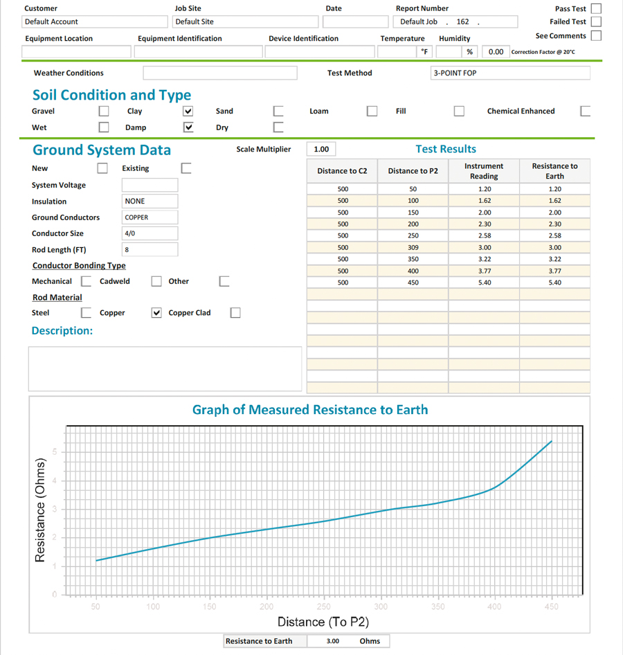
It is also possible that the data/curve is affected by other buried objects. Ensure you are paying attention to the test area and noting buried pipelines, fences, etc., that could affect the results. This report is also missing information required to verify or replicate the results. The site address (or GPS coordinates), test direction, and current probe placement are not included. Since the size of the site could not be verified, it is also possible that the current return probe was not placed far enough away from the site under test — a very common testing mistake.
Example 2 – Site Not Isolated
An engineering firm was hired to perform FOP testing on the two substations with a shared ground grid (Figure 3, red squares). The larger red square is the collector yard, and the smaller one is the utility’s point of interconnect (POI). The diagonal of the two substations is 500 feet, so the planned FOP current probe was placed 2,500 feet away (green line). The measured impedance was reported as 7.4 ohms while the design value was 0.89 ohms. This discrepancy in values was a red flag that something was off.

Figure 3: Nearby sites must be investigated for potential bonding to the site under test.
Next, a testing firm was brought in. They essentially repeated the same method, going in a different direction with their current wire (yellow line). They obtained a value of 1.48 ohms at 62%. This value was lower but still above the desired 1-ohm design value.
Next, we were hired to test this site with the specialized, computer-based smart ground multimeter (SGM) prescribed in IEEE Std. 81. After our initial test, a high error in the SGM data reported by the SGM software indicated that something was amiss. We discovered that the solar arrays were bonded to the inverters, which were then bonded to the substations through the concentric neutrals. The new diagonal of the combined sites is now 6,600 feet. For FOP testing, the current return probe should have been placed at five times 6,600 feet, which equals 33,000 feet or 6.25 miles (Figure 4).
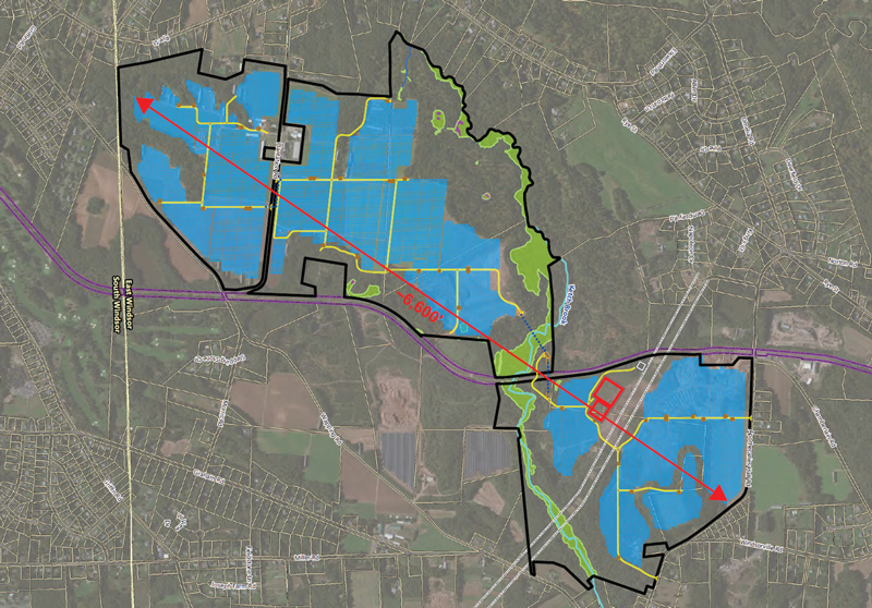
The site had a significant amount of metallic interference, including fencing (black lines), railroad tracks (purple line), a transmission line (dashed white lines), and the arrays themselves (blue figures). Due to the size, surrounding interferences, and the fact that the utility’s substation was bonded and energized, it is impossible to test this site with the FOP method.
The SGM allows testing in these conditions if aided by a software model of the ground grid and other connected sites and grounded objects. We reduced the required remote earth distance by disconnecting the concentric neutrals from the inverters, isolating the substation grids from the solar arrays. Although we were still bonded to the utility system, the site could now be tested with the SGM. We measured 0.74 ohms versus the design value of 0.89 ohms.
PLAN FOR SUCCESS
Preplanning can go a long way towards testing success. For any large site such as a solar farm, wind farm, generation plant, urban location, campus, or other complex site, ask lots of questions!
- Get a site address and GPS coordinates and look at the site on Google Earth; drop in street view if available. Identify nearby challenges such as:
- Possible interconnected substations/buildings/arrays
- Fences
- Pipelines
- Transmission/distribution lines
- Review the Geotech report and soil resistivity data, if available.
- Verify through testing that the site under test is isolated.
- Determine the diagonal of the site and the distance required for the current return probe; make sure you take enough current-return wire.
- Determine the test path and property access requirements.
- When on site, previously unknown challenges may require a change in the test plan.
CONCLUSION
Many project specifications will call for the FOP test. Know its limitations, be familiar with IEEE Std. 81, and follow best practices for a successful outcome.
REFERENCE
- IEEE. IEEE Std. 81–2012, Guide for Measuring Earth Resistivity, Ground Impedance, and Earth Surface Potentials of a Grounding System.

Jacob Rioux is a Grounding Specialist at Hood Patterson & Dewar, Inc. With a background in substation design and testing, Rioux provides substation and facility grounding system testing and safety analysis. He also performs soil resistivity testing and grounding system design for new construction. His client base includes electric utilities and industrial and commercial facilities. He provides grounding articles, training, and presentations for conferences and clients nationwide. Rioux has a BS in mechanical engineering technology with a minor in electrical engineering technology from the University of Maine.