
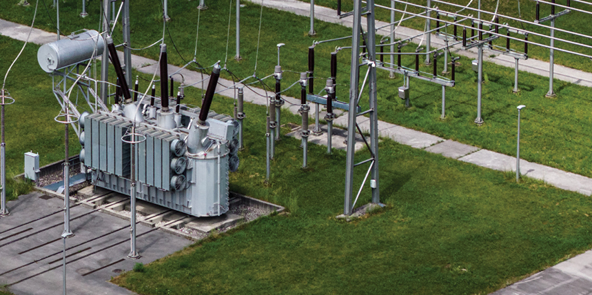
Utility and industrial substations are made reliable through testing and validation at each stage of their life cycle. Each stage has its own opportunity to avoid nuisance issues or catastrophic failures. Acceptance testing determines whether the substation starts out as designed. Routine inspections monitor whether it stays that way. Maintenance testing determines how well we understand its condition as it ages.
The misses rarely look dramatic when they begin: an alarm wired to the wrong indicator, an annunciation no one chases, a pass/fail test result accepted as the whole answer. Diane Vaughan’s study of the Challenger disaster, which coined the phrase the normalization of deviance, showed how tolerated deviations like these compound until something goes badly wrong. Once an incident begins, the outcome is largely a matter of luck.
This article follows a substation’s life in that order, with field stories from each stage and the newer testing technologies that are changing what maintenance test results can uncover. The aim is a virtuous cycle in which each stage’s findings strengthen the next, improving substation safety and reliability.
ACCEPTANCE TESTING
Acceptance testing sets the tone for everything that follows. It is the best time to find a problem, and it produces the baseline data that every later inspection and maintenance test will be compared against. A substation that starts with proper documentation, a verified functional design, and a correct installation has a reference point for its entire life.
Component testing confirms that transformers, circuit breakers, and other apparatus were undamaged in shipping and installation. What matters more is whether the controls and functions work as a system, and that is the one place acceptance testing should never be compromised. Functional testing takes time: every circuit, input, and output must be exercised and confirmed. This builds confidence in the system being turned over. The strongest program I have seen functionally tested the equipment three times: at the factory, after assembly into the e-houses, and finally onsite, verifying every external input and output. Each pass found something the last one missed, or something that wasn’t yet a variable at that stage. Consider the following examples from the field:
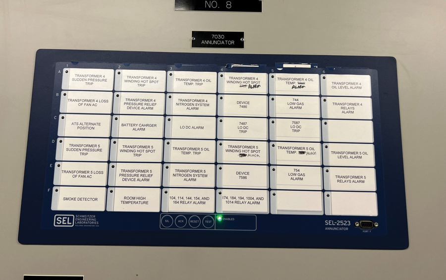
A technician once operated a transformer’s mechanical alarms and walked to the panel to confirm the indicators were lit. They did, and a wiring error went unnoticed. A second pass, operating each alarm independently, exposed it: the low oil alarm stayed dark while the winding temperature alarm lit (Figure 1).
On more than one substation that I have started up, acceptance testing found breakers installed backwards: once by the contractor for convenience, once from a mirrored drawing by the designer. Either way, the CTs feeding the differential circuit were wired to the wrong bushings (1, 3, 5 versus 2, 4, 6).
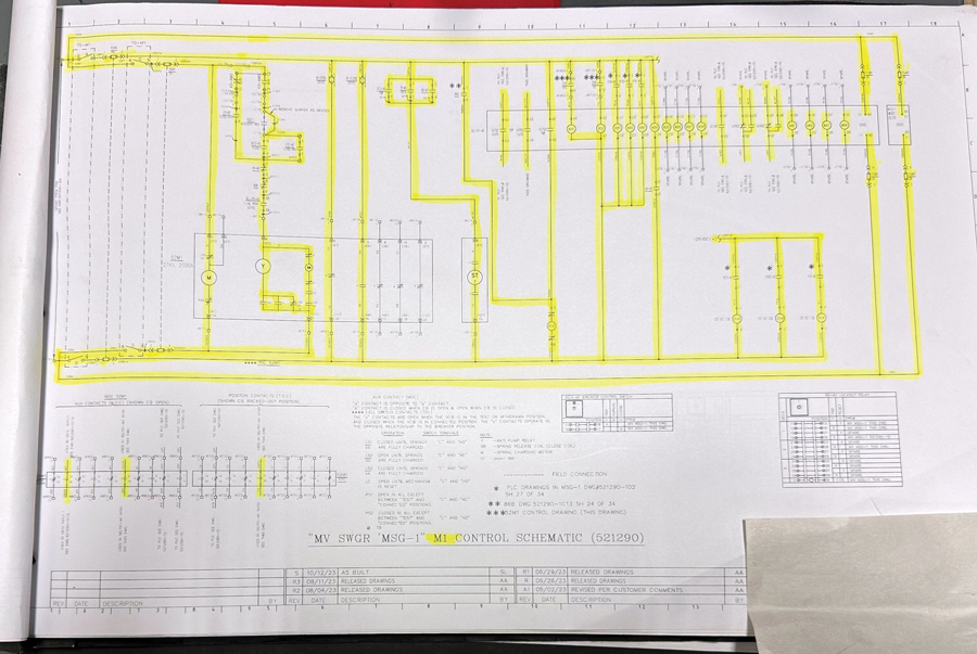
While I was reviewing functional testing on one project, a breaker was opened and showed red and green indicating lights simultaneously. The technician in charge did not investigate at the time, and it took an independent verification program to find and correct the wiring fault. One habit helps: yellow-line the drawings (Figure 2) with an actual highlighter as each circuit is verified.
Verify shorting blocks and test switches in both the open and closed positions. I have found many miswired so they failed to short the CTs, which can lead to dangerous failures. Verify single-point grounding on simple and differential circuits alike, since multiple grounds can cause misoperation during faults.
In addition, pay particular attention to PK-style CT shorting blocks. I have found many with the shorting bar on the wrong side of the circuit and, more subtly, installed backwards (Figures 3 and 4). The point of the bar should face into the block, not out.
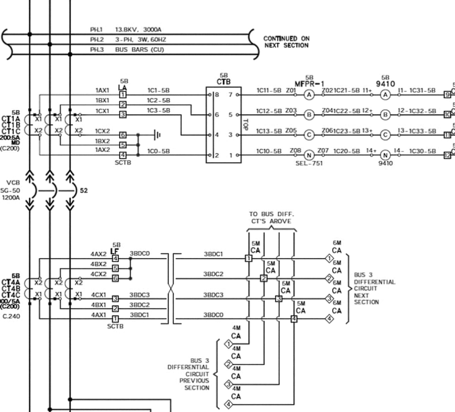
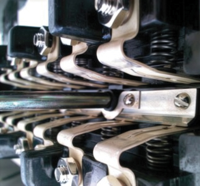
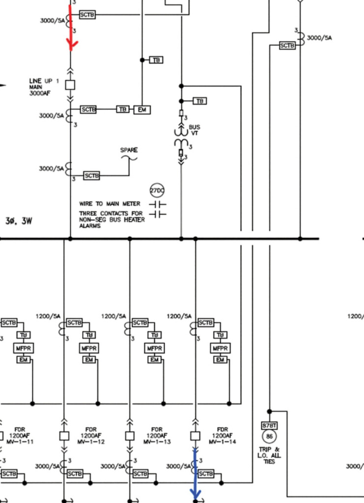
Finally, for bus differential systems, primary current injection is the most practical way to confirm CT polarity and wiring (Figure 5). Inject primary current through each phase of the main breaker and out each phase of each feeder breaker. This verifies the entire system in a way individual component testing cannot.
ROUTINE INSPECTIONS
If acceptance testing sets the tone, routine inspections catch small problems before they become failures. Something as simple as a decaying filter, a corroded battery post, or a space heater that has quietly stopped working can start causing damage that no one sees until it is serious.
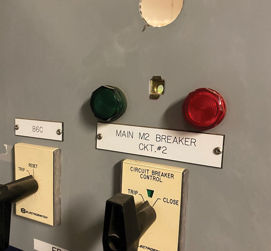
Alarms and indicators need attention long after acceptance testing ends. One client’s transformer annunciators would randomly and mysteriously alarm. Left unresolved, this kind of normalized issue erodes confidence in the monitoring system and invites operators to silence or ignore a real problem. Control lights also carry more information than most technicians give them credit for. Beyond breaker status, they indicate trip coil health and the presence of control voltage (Figure 6). Relay targets and self-test warnings deserve the same attention on every visit.
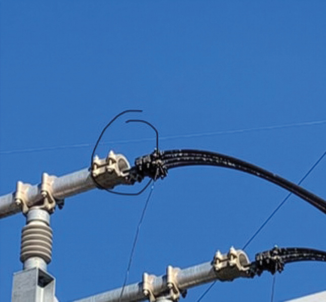
Infrared inspection is one of the highest-value routine tasks a crew performs. In one case, a secondary bus connection on a utility transformer was found running dramatically hot. Had it failed, the entire system would have lost at least a phase, and customers would have lost power. Because periodic surveys have blind spots between visits, critical systems are worth upgrading to continuous online thermographic monitoring, which provides 24/7 visibility rather than a snapshot at each interval (Figures 7 and 8).
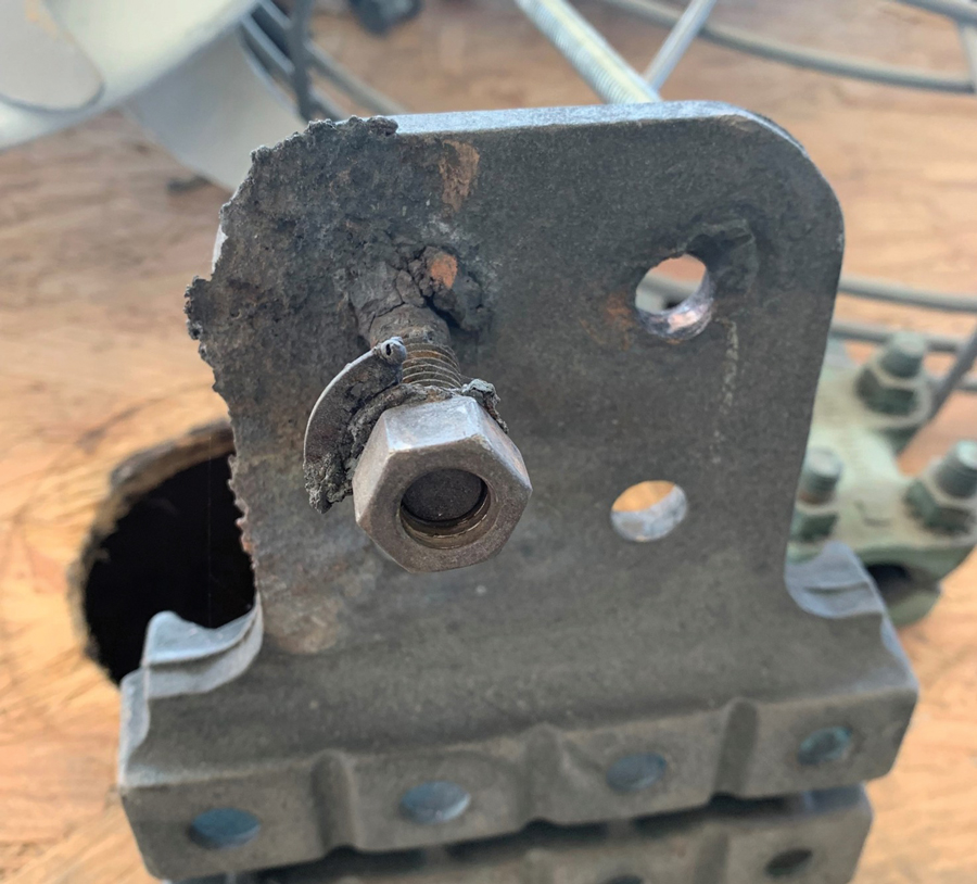
Poor cable insulation, often on top of a transformer and inaccessible without an outage, has triggered sudden-pressure devices during heavy rain, tripping the transformer offline and forcing an extended outage while the cause was identified (Figure 9). In another case, differential electromechanical relays misoperated because underground CT wiring from a remote breaker had degraded until the circuit was effectively open.
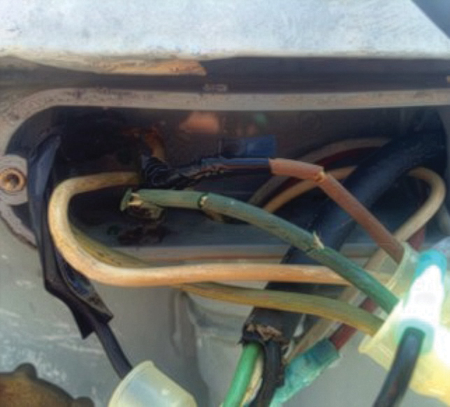
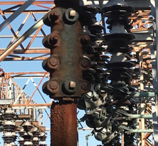
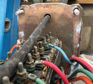
Mechanical inspections round out the routine inspection program. A rusting switch operating rod or fence post is not only an environmental issue; it can point to ground current that needs to be addressed. In one case, a rusted rod was found only when it broke during an attempt to open the switch for maintenance. Uncommon causes matter too: a ground switch misoperated after wasps built a nest in its mechanism (Figures 10 and 11).
MAINTENANCE TESTING
Early in my career, maintenance testing was simpler. A vacuum breaker meant a bottle integrity test, pass or fail. A power transformer meant a winding power factor test, and 0.5% was good enough to walk away. Ratioing a load tap changer transformer meant hand-cranking a single-phase TTR one tap at a time.
What has changed is how much information we collect. We don’t get many chances to rely on feelings or opinions in this line of work. As the saying goes, “In God we trust; all others shall bring data.” Data is most useful in context. When a technician gets hung up on a bad result, I encourage them to keep testing. If you stop at the first high-voltage bushing to chase a bad reading, you never learn how the other two compare, and you can’t be certain whether you’ve found a problem or made a mistake. A bad result is a question, and the rest of the data is the answer.
TRANSFORMER INSULATION DIAGNOSTICS
Today, power factor testing can tell us more. When test sets began sweeping across a range of frequencies, there was often pressure to run only the 60 Hz point and move faster. I held to the sweep in most cases. Yes, it takes a little longer, but it shows far more. On one customer’s transformer, the H2 bushing’s 60 Hz power factor was elevated enough to fail on its own. The sweep added detail: H1 and H3 stayed flat near 0.2% from 15 to 400 Hz, while H2 climbed to about 3% at 15 Hz. The two acceptable bushings made the third stand out, and the low-frequency rise gave the customer a stronger case for replacing it. The pushback is nearly always time, but we have the time it takes to get the data that lets the customer make an informed decision about the safety and reliability of their system.
A 15 to 400 Hz sweep is only the start. Dielectric frequency response (DFR) measures from well below 1 Hz upward, and the shape of the curve shows how much moisture the insulation holds. That matters because most of a transformer’s moisture lives in the paper, not the oil. One case study I reviewed described a 150 MVA unit with about seven tons of cellulose and 70 tons of oil. At 40°C, the oil held about 1.1 kg of water, and the paper about 210 kg. An oil sample can look acceptable while the paper is wet, and moisture moves between them with temperature, so one result at one moment can’t settle the question. At 70°C, dry insulation supports roughly 100 years of life; at 3.4% moisture, about 15 years, an 85% loss.
BEYOND PASS/FAIL TESTING
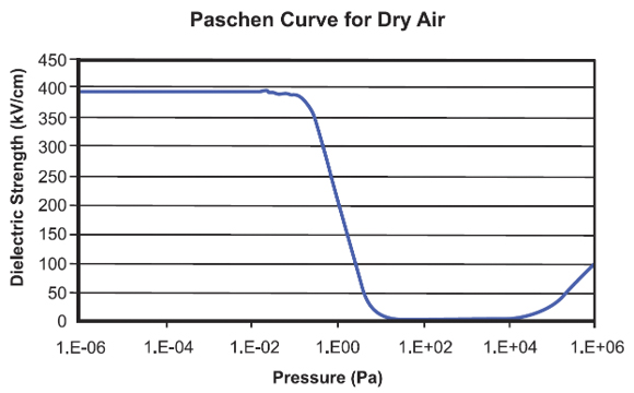
Vacuum bottles show the same shift away from pass/fail. In nearly 30 years, I’ve had two circuit breakers fail the AC high-pot integrity test. It gave us a go/no-go answer and nothing else. Previous passing results couldn’t tell us how long those bottles had been degrading. Magnetron atmospheric condition (MAC) testing, built on the Penning discharge principle, measures the actual pressure inside each bottle. Compared against the Paschen curve and trended across periodic tests, the readings show pressure rising and let us plan a replacement instead of finding out the hard way (Figure 12).
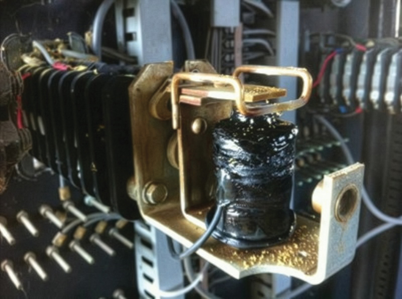
Relays have taken two paths. Electromechanical relays still need constant attention to stay on their time/current curves. They can drift and require adjustments or upgrading to a modern replacement. With microprocessor relays, we worry less about the protective elements and logic once a substation is properly commissioned, so testing has moved toward pass/fail: verify metering, inputs, and outputs. This is where a tempting shortcut hides. On one test, a relay failed to operate its 86 lockout. It was determined after investigation that the 86 had been improperly reset, which burned out its coil. We found it by exercising the output and protective element through to the controlled device, the 86, not just watching the relay’s output (Figure 13).
ANSI/NETA MTS, Maintenance Testing Specifications for Electrical Power Equipment, says to check relay outputs, preferably by operating the controlled device. It leaves verifying each protection element optional. The required tests mostly tell us whether the equipment passes, and the optional ones tell us how it is aging. The tools are already in the standard. If you’re using them, I’d like to hear what you’re seeing.
CONCLUSION
Reliability is built into a substation, not assumed. It happens the same way at every stage: someone chooses to collect the data and act on it. At acceptance, that means proving the system as a whole and protecting the time to do it. In service, it means treating an alarm, a warm connection, or an odd noise as information to act on, not to dismiss. In maintenance, it means taking advantage of available technology to determine how equipment is aging, not just whether it meets industry standards.
Each stage hands something to the next. The baseline captured at acceptance is what makes a sweep-frequency response fingerprint meaningful years after a fault. Inspections show maintenance where to look. Maintenance results tell the owner where to act before a failure does. A deviation caught at any of these points is one that never gets the chance to become normal.
The tools will keep improving. The question beneath every test stays the same: is this result telling us what we need to know? Asking it, and taking the time to answer it, is how we keep the people and equipment on these systems safe, and it is why we go out to test.
REFERENCES
Hond, Paul. “How the Challenger Disaster Became a Case Study of the ‘Normalization of Deviance.’” Columbia Magazine, Winter 2025–26. magazine.columbia.edu/article/challenger-disaster-normalization-deviance.

Mose Ramieh is Vice President of Business Development at CBS Field Services. A former Navy man, Texas Longhorn, Vlogger, CrossFit enthusiast, and slow-cigar-smoking champion, Ramieh has been in the electrical testing industry for more than 25 years. He is a Level IV NETA Certified Technician with an eye for simplicity and utilizing the KISS principle in the execution of acceptance and maintenance testing. Over the years, Ramieh has held positions ranging from field service technician, operations, sales, and business development to company owner. To this day, he claims he is on call 24/7/365 to assist anyone with an electrical challenge. That includes you, so be sure to connect with him on the socials.