

With electromechanical and solid-state protective relays now obsolete and nearing the end of life, upgrading to microprocessor counterparts is paramount for the reliability of power systems. Microprocessor relays provide advanced communication, monitoring, and automation capabilities along with all basic protection and control platforms.
Raising awareness among customers about the importance of a relay upgrade is vital in the overall contribution to power system reliability. Line relay upgrade projects involve not only the customer, but the utility provider as well. These highly technical projects tend to be more complicated and involve more than one entity. Rrelay upgrade projects can yield maximum benefits if carried out as a team effort among the customer/end user, engineering firm, commissioning agent, and the utility provider.
This article presents a case study of a line relay upgrade project that lay dormant for 15 years and was revived in 2021. The line relay was installed and wired in 2004, but was never commissioned or put in service. After the new relay was tested and commissioned, a functional check and testing were performed on its associated DC circuit. End-to-end testing was completed with the utility provider, and the relay was prepared to be put into service. The process was unique: All testing and commissioning were performed while the substation was energized.
This article focuses on the steps taken to isolate the relay and maintain power system reliability, as well as the procedures performed to gather onsite data and raise the customer’s awareness of the importance of upgrading. The detailed procedures to complete the upgrade process, challenges faced, and lessons learned are also outlined.


INTRODUCTION
Protective relays are an integral part of the power system; they ensure protection for equipment during fault conditions. If these protective devices are installed, engineered, programmed, and maintained properly, they keep our power system safe and reliable.
It is critical to upgrade protective relays to the current technology and standards. Many electromechanical and solid-state relays are becoming obsolete, which means upgrading them is inevitable, through unplanned failures or during planned outages.[1] Older protective relays near the end of life cannot be relied upon for equipment protection. Instead of providing system protection and reliability, these relays now become a liability.
Older electromechanical line relays have limited functionality and capability, which is another challenge when integrating them with new microprocessor relays installed by the utility provider. System integration is especially challenging in the case of line relays, since these relays usually protect the same transmission line. Most advanced relays can detect and interrupt the fault more quickly than their electromechanical counterparts. Microprocessor relays also provide advanced communication and automation abilities. This means the relays can be used to gather data for event analysis, power quality monitoring, and diagnostics, all contributing to power system reliability.
Relay upgrade projects require meticulous project planning that includes gathering field data, communicating with all stakeholders early and often, and preparing testing and commissioning plans. This process was especially important in this project because it involved reviving an existing incomplete project and included line relaying. Most relaying schemes and configurations impact one power system or entity; line relaying affects more than one power system because a line connects two or more entities. In most cases, the other end of the line is a utility provider, as was the case in this project.
Another project highlight was raising awareness about the importance of relay upgrade, as the process that was undertaken was more significant compared to the actual on-site testing and commissioning process.
PROJECT BACKGROUND AND SCOPE OF WORK
The current incoming power for the customer’s plant is supplied by a 69-kV switchyard (Figure 1) that consists of a 1200-ampere (A) main incoming oil circuit breaker (OCB), six step-down power transformers, six OCBs on the primary side of these transformers, and the associated substation that houses protective relaying and metering circuits. All transformers are protected by advanced microprocessor transformer differential protection relays as primary and electromechanical overcurrent relays as a backup.
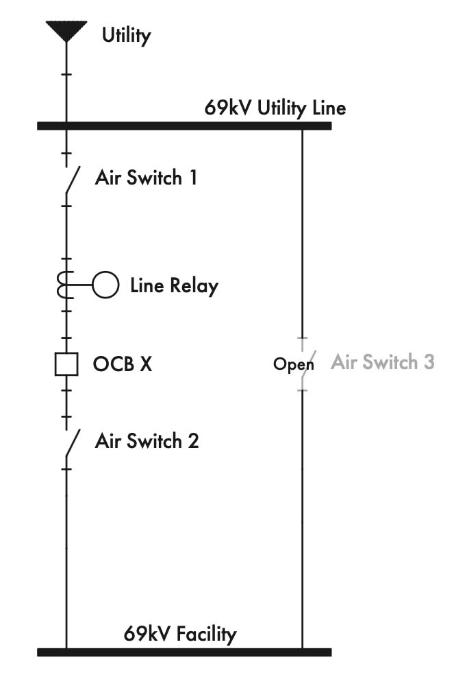
The main OCB—called Breaker X for the remainder of this article—has microprocessor relays for overcurrent protection and line protection in conjunction with the utility company. There are also three air switches in addition to the main incoming OCB. The way these air switches were designed was critical to this entire testing and commissioning project.
Project Background
Currently, two electromechanical relays (KD-10s) in the facility’s substation provide primary protection. These relays only provide phase-to-phase and three-phase protection and operate in different zones: Zone 1 and Zone 2. Zone 1 protects up to 80% of the line to the utility substation #1 and operates instantaneously for a fault on the line. Zone 2 protects the rest of the line, but before it opens breaker X, there is a 40-cycle delay. This is too much time for clearing a fault. With a new microprocessor relay and communication to the utility company, the clearing time could be reduced to three or four cycles.
The new microprocessor relay will provide the same functions as the two KD-10s, as well as phase-to-ground protection. Since it is believed that approximately 70%[3] of faults on an electrical system are line-to-ground faults, this protection for the facility is critical. The two KD-10s will remain in service and provide backup to the new microprocessor relay.
The microprocessor relay currently installed in the substation provides no protection since the trip cutoffs are lifted; this relay has been left in this state for many years. During the initial site visit, we were told that the initial relay upgrade project was carried out sometime around 2003–2004. This was the date and timeframe mentioned during site visits and in the drawings.
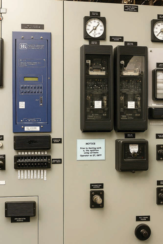
The relay upgrade included new microprocessor relays and associated test switches to provide isolation for trip outputs, currents, and potential inputs. The system has two test switches. The top test switch shown in Figure 2 is designated for the currents and voltage; the bottom test switch is designed for the trip circuits.
During the initial design and upgrade process, this relay was intended to communicate over radio controls to the utility company. An antenna and radio frequency transmitter in the substation were installed but never commissioned or used in all these years because communicating over the radio was not considered reliable. The utility company has installed a fiber communication cable between its substation and the facility’s substation. This newly installed fiber should alleviate any concerns about the reliability issues for communicating between this relay and the utility relay.
Scope of work
The main scope of this project was to reboot this relay, which has been dormant for several years, and make the system fully functional so the relay upgrade project could be implemented in the plant’s power system reliability. We have an excellent relationship with the operations and maintenance (O&M) and engineering teams for this facility. Both of these teams asked for our assistance with two specific requests:
- Create a feasibility and plant reliability (MV relaying) report to convince their upper management to implement this project.
- Prepare the testing and commissioning plan, including end-to-end testing with the utility.
Thus, the end goal of this project was to integrate the microprocessor line relay into the plant’s power system in conjunction with the utility company to improve the plant’s reliability.
PROJECT PLANNING AND PREPARATION
This was not a typical relay upgrade project. The initial goal involved preparing a feasibility study on the project itself as well as educating plant upper management on the importance of this project and how it could be executed successfully. After all commercial items were taken care of, there was productive communication with plant engineering and the O&M team, and the utility company was brought into the conversation. The utility company was very collaborative and provided its full support.
Site Visit, Data Collection, and Findings
The plant facility engineering and O&M teams were instrumental in providing most of the existing project drawings and documents. The site visit was performed for an entire week. The main intention of the site visit was to gather hard copies of all drawings, download relay settings, verify the relay wiring, verify the test switch position, and similar tasks.
I have always believed in site visits, and customer interaction is the best way to execute any relay commissioning project. Non-intrusive data collection was performed on site. We communicated with the existing microprocessor relay, downloaded relay settings, and provided them to the customer and the utility company. The relay was enabled and seemed to be working fine, although there were some questionable wiring connections in the back of the new relay and a couple of wire jumpers. Some modifications had been made on the system, but had not documented in the as-built drawings. All changes were redlined in the drawings, and baseline voltage measurements were performed in the DC trip circuits.
Presentation to Plant Upper Management
After concluding the week-long data collection process, a detailed feasibility report was created and presented to the facility’s upper management. Several facility leaders, the engineering and O&M teams, and utility company representatives participated. A few of the meeting highlights are provided here:
- The biggest risk of not improving the system is that when there is a fault on the line between the utility’s substation and the facility, the utility company may open the breaker on their end while the mill’s generators continue to feed the same fault. This is because the protective relays on the mill’s incoming breaker (OCB X) have to perform independently and take longer to operate. This could cause substantial damage to the generators and electrical system.
- All testing and commissioning tasks could be performed without any power interruption to the facility. One of the main reasons this project was not completed despite several past attempts was that the power could not be shut down. Note that the term “outage” typically means turning the power off; however, in this article, outage does not imply any power interruptions; it simply refers to the testing and commissioning task.
- A microprocessor relay has a wider variety of protection functions, including Zone 1 through Zone 4 protection schemes and neutral and ground overcurrent protections. KD-10 has limited capability.
- The microprocessor relay provides various communication parameters and input monitoring capability, including sending relay failure and loss of communication alarms. None of these is possible with KD-10.
- For the utility breaker trip at the utility substation, the utility trips the breaker at the substation and sends a direct trip (DT) signal to the microprocessor relay, which trips OCB X at the customer switchyard. This relay would also send a signal to the load shed system, initiating the load shed scheme. This event would be captured in the sequential event recorder to assist with troubleshooting.
The meeting was very interactive. Every possible effort was made to describe the importance of this project and the methods of effective project execution. A frame of detailed isolating, relay testing, commissioning, and end-to-end testing was presented. A few weeks after the site visit and presentation, we were notified that the plant had provided notice to proceed with the testing and commissioning items of the project.
Main Incoming OCB and Relaying Circuit Isolation
A detailed plan was prepared for isolating the microprocessor relay and OCB X from the main incoming power system. OCB X was part of the isolation so that all DC functional trip checks[4] could be performed on the entire OCB control scheme along with relay testing. A few main highlights of the system isolation plan are provided here:
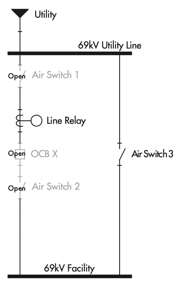
- Feed the plant through the bypass switch, close air switch #3, and open air switches #1 and #2. The facility would prepare these switches for operation.
- Isolate breaker failure trips, direct trips, breaker failure initiates, and load shed initiates from the microprocessor relay to OCB X using test switches XA and XY. Open all knife switches first in test switch XA, and then XB. Turn the 43 CO breaker failure cut-off selector switch to the OFF position. This provides two isolation points in a trip circuit.
- Disable the bus differential tripping scheme using test switch XB. Pull the knife switch named TRIP first, then all current inputs. This should prevent any trips on the 86B bus differential lockout relay and consequently on all OCBs.
- Disable undervoltage (27) from the 69-kV bus using the isolation switches at the bottom of the 27 Westinghouse CV-2 relay. Switches #1 and #10 will be pulled, and this relay won’t be able to send any trips to OCBs.
- Work with the facility to disable all DCS trips and handle any load shedding manually.
COMMISSIONING AND TESTING PLAN
Switching Order
An additional switching order was prepared to help the facility switch air switches. The facility now has a step-by-step procedure to follow when bypassing incoming breaker OCB X, using kirk-keys to ensure that the procedure is performed in the correct step-by-step order. Existing relay settings were reviewed, and recommended settings changes with minor modifications were sent to the customer and the utility company.
A detailed switching order was created for the initial pre-testing circuit isolation and as a post-testing plan for restoring the circuit to as-found condition. Some of the detailed steps from the switching order are provided in Table 1.
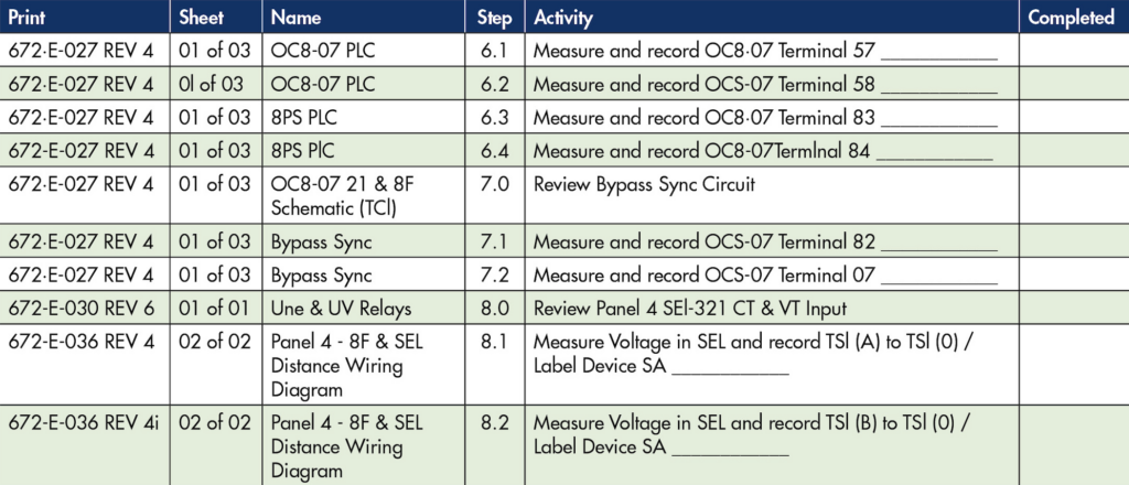
This switching order, which contains several chronological steps, was peer-reviewed internally and provided to the customer for further feedback and review. The switching order was provided to the utility company for review and comments. After subject matter expert (SME) and technical reviews, the final version of the switching order was provided to all affected parties. It also included the step number, drawing references, drawing title, and switching activity, such as opening test switches, measuring voltages, etc.[4]
On-Site Relay Testing
Part of the commissioning plan was to retest the new relay, verifying its parameter settings with the associated trip levels and functions, including the function with the utility company initiating a trip command for our incoming breaker OCB X when their feeder breaker opens.
A mirrored-bits communication scheme was used, which means that the utility company will send bits reflecting the open/closed status of their breaker. This is a common way of communicating between substations. When the relay receives the open bit because of a detected fault and trip command from the utility substation, the facility’s OCB X should trip as well. The utility should not be allowed to reclose the facility’s tripped breaker. After the utility company has reclosed its breaker, the powerhouse operator will reclose OCB X when synchronized with the generators.
Commissioning
After a few attempts to schedule onsite testing, a date was secured to perform onsite tasks. The switching order was followed to isolate the circuit. The relay apparatus testing was performed according to NETA standards, minor wiring changes were made, and DC functional trip checks were accomplished. The DC trip checks were performed for all circuits from the relay to the OCB X. All tests were successful and went as planned.
End-to-End Testing
End-to-end testing was performed with the utility provider. Some complications were noticed with the utility company commissioning team. During the end-to-end testing, an actual utility-initiated trip command was planned. This means the utility will actually trip their feeder breaker at their substation, and it will be verified that the facility’s incoming breaker OCB X will trip as well. The utility company ran into some technical difficulties and was not able to simulate and send the fault to the customer’s circuit. Despite several attempts, they could not send the trip signal. After several hours of troubleshooting and meetings with the customer and utility company, a consensus was reached to restore the system to normal configuration and complete the end-to-end testing at a later date.
This project was also an opportunity to perform preventive maintenance and testing on all three air switches and test the DC schematic circuit for the OCB. A light form of preventive maintenance, such as visual and mechanical inspection, lubing connection points, etc., was performed on air switches. DC functional trip checks were performed on the OCB control circuit. These tests are vital from the regulatory standpoint and to extend equipment life span.
FUTURE WORK AND LESSONS LEARNED
In addition to the goal to complete the relay upgrade project that was started several years ago without any power interruption or cold outage, another important project goal was to create a trusted and verified switching order for the main incoming OCB X so that the facility could perform preventive maintenance and testing in the future. The facility was very pleased with the way the project was carried out and the goals that were achieved. A few months later, the facility was able to replicate the power isolation process and complete the testing with the utility. This system is now fully functional and operational.
One of the important lessons learned was that projects like this require meticulous and detailed planning, effective communication, attention to detail, and perseverance. Raising awareness of stakeholders about the importance of their asset, the need for periodic preventive maintenance, and a timely update/upgrade goes a long way in making our electrical system safe and reliable.
CONCLUSION
Protective relays are the backbone of the protection, automation, and control for medium-voltage systems. They are critical to power system performance and reliability; thus, utmost importance should be given to the proper maintenance and upgrade of these relays. It is our responsibility to not just perform the preventive maintenance and testing/commissioning of power systems, but also to make our customers aware of the necessity and impact this could have on their system reliability. Using engineering brainpower and harnessing the advancement in technology, we can keep our electrical system reliable and extend its lifespan.
REFERENCES
- Daniel L. Ransom, PE. “Upgrading Relay Protection? Be Prepared,” 66th Annual Conference for Protective Relay Engineers, College Station, TX, April 8–11, 2013.
- SKM Systems Analysis, Inc. SKM Power Tools: Power System Software and Arc Flash Hazard Analysis and Design Solutions.
- L. Bangar Raju and K. Subba Rao. “Evaluation of Passive Landing Detection Methods for Line to Ground Unsymmetrical Fault in Three-Phase Microgrid Systems: Microgrid Islanding Detection Method,” Engineering, Technology and Applied Science Research, October 2021.
- Karl Zimmerman and David Costello. “Lessons Learned From Commissioning Protective Relaying Systems,” 61st Annual Conference for Protective Relay Engineers, May 2008.

Bibek Karki is a Regional Director of Engineering at IPS PowerServe, where his responsibilities include power system and coordination studies, motor starting, harmonic wave, and arc flash hazard analysis using SKM, Easypower, and ETAP. He has 12-plus years of experience in power system studies, electrical testing, and the maintenance industry, and has performed preventative maintenance, installation, modification, testing, and repair of electrical switchgear, circuit breakers, transformers, protective relays, and associated power distribution equipment from 480 volts through 345 kV and up. Karki previously worked as an Electrical Safety Engineer/SME at Lawrence Livermore National Laboratory. He is a NETA Level 4 Certified Senior Technician, a NICET Level III Technician, a Registered Professional Engineer in 26 states, and an IEEE Senior Member. He graduated with an MS in electrical engineering from Southern Methodist University. Karki was recognized as a 40 Under 40 by Consulting Specifying Engineer in 2022.