
Electrical power systems, regardless of the industry (utility substations, industrial metal-clad switchgear, hospitals, data centers), are built with crucial auxiliary systems. These systems are dependent on each other to ensure these power users have electrical systems that are safe and reliable.
The DC battery system might be one of the more critical of these systems. DC batteries provide power to protective relays, breaker trip circuits, and other vital control systems. If these battery systems are not properly maintained and monitored, the safe operation of the entire power system will be placed in jeopardy.
Throughout my career, I have seen battery issues from minor to potentially catastrophic.
OUT OF SIGHT, OUT OF MIND
Over the years, we have seen locations with fine maintenance practices, but yet deficient battery strings. This typically occurs when these battery systems are placed behind doors or covers.
One manufacturing facility suffered a catastrophic failure of their switchgear because of a loss of control power. The loss of control power to the medium-voltage switchgear created a situation where the electromechanical protective relays operated during an overcurrent condition in the system, but there was no DC control power to trip the breakers. This inability to trip the breakers allowed the fault to persist, doing more damage, until the fault was finally cleared by the upstream utility fuses.
The battery system had been completely forgotten for years because it was located in the rear of the switchgear behind a bolted cover. Photo 1 shows the battery with the cover removed.
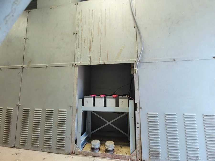
Photo 1: Battery Behind Cover
While this is an odd place to locate the battery system, it is not entirely rare (Photo 2). Here, the middle door hides the battery system.
![]()
The best solution is to place battery systems where they are visible during a standard system walk-through. In substations, these battery strings are typically located on the floor of the substation room and are completely visible so that even minor issues can be observed (Photo 3).
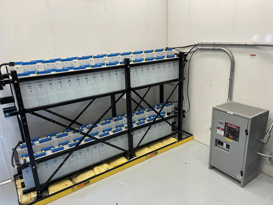
Photo 3: Well-Placed and Visible Battery System
Technician Pro-Tip
There were visible warning signs that the DC control power had failed. Unfortunately, those responsible for monitoring this power system were not familiar enough with how to recognize the warning signs. You might be guilty of this if you have ever ignored a breaker with a red (breaker closed) light that is not illuminated. This could be something as simple as a blown lamp. It could also be something as critical as a bad trip coil or a complete loss of control power, as was the case in the preceding story.
BATTERY NEGLECT LEADS TO CORROSION
Photo 4 shows the worst case of battery corrosion I have ever come across. As you can imagine, this power system had been neglected with no service or inspection for many years.
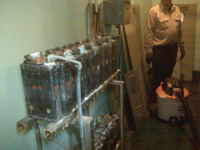
Photo 4: Corrosion Due to Neglect
This facility did not have the trained personnel necessary to ensure the system was properly maintained. This system was discovered by our team when we were called in to provide flood recovery efforts. If not for a flood, this power system’s negligence would have continued until something bad happened.
All power system safety and reliability starts with good housekeeping. When it comes to DC battery systems, a great deal can be learned, and issues can be headed off, from routine visual inspections:
- General corrosion on battery posts
- Other cracked or damaged internals such as a cracked internal seal (Photo 5)
- Acid levels not between the high and low marks (Photo 5)
- Damage to plates including positive plate growth
- Bright lead-sulfate crystals on the negative plates indicating battery undercharging
- Material, particularly on the bottom of the battery, creating an potential short between plates
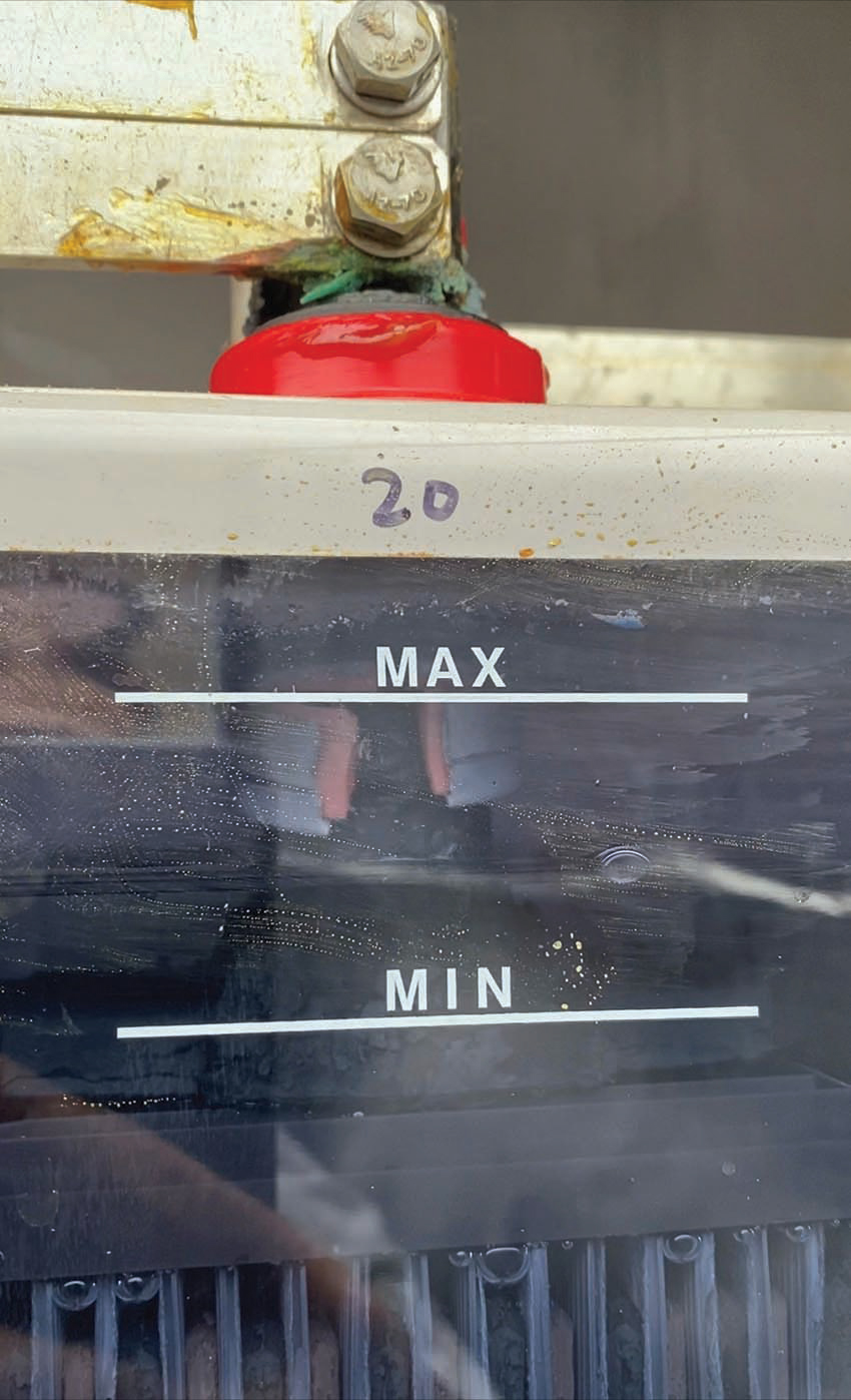
Photo 5: Damaged Internal Parts
LACK OF BATTERY MONITORING
This case took place over 10 years ago when communication technology isn’t what it is today, but it is still no excuse for what occurred at a local utility customer.
The utility was making a system modification that necessitated de-energizing the control power transformer. “No problem, right?” they asked. “Our substation doesn’t need AC power except for lighting and air conditioning the relay control house.” Of course, this also created a loss of AC power to the battery charger.
During a short window — from a few hours to even as much as a couple of days — this is not an issue. Leaving the battery system with the charger off causes the battery string to be slowly depleted (in this case, over the course of the weekend). This slow depletion of the batteries created a DC undervoltage condition that — left unchecked and uncorrected — led to protective devices tripping off the entire substation. This interrupted power to thousands of customers. Recovery efforts included having to bring in a portable generator to power the charger and allow relays to be reset and breakers closed.
Most power system designs include DC battery-voltage monitoring by the protective relays. Those same systems will also trip breakers before the DC control power becomes too low to protect the system from being in a configuration where the breakers would not trip.
Exponential improvements in communication technology can and should be utilized to provide early warning for this type of system issue so it can be headed off. In this case, a text message to the substation supervisor would have allowed an intervention to head off the system tripping itself off-line. This idea of continuous monitoring extends beyond DC battery strings, and I’m excited to be a part of discovering how the industry will utilize continuous monitoring and notification.
INSPECTION AND TESTING
Additional inspections and testing that can be performed vary from easy to difficult:
- Note any indicator lights on the battery charger that represent a fault condition and/or error codes on a display. Avoid normalizing deviation and maintain an error code and fault-free system. Positive/negative DC grounds are one example of errors that can be difficult to resolve. Troubleshooting this type of error takes time and the ability to isolate portions of the system to locate and correct the ground.
- Measure the voltage of the entire battery string with the charger DC output breaker off.
- Measure the voltage of each half of the battery string. This value should be roughly half of the measurement of the entire string. Any significant variation should be investigated by measuring the voltage of each cell (which is also an option; it just takes longer).
- Measure the charger output for AC ripple. Excessive AC ripple can shorten battery life by creating a situation where the battery is repeatedly undercharged and discharged.
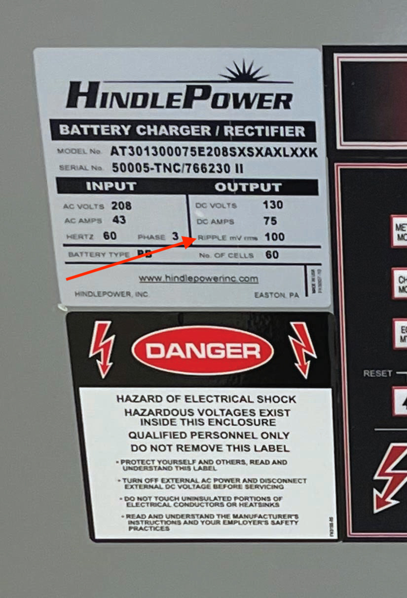
a. C&D Technologies recommends that a maximum ripple of 1.5% of the voltage be allowed during the bulk phase of the charging and a maximum of 0.5% voltage ripple during the float phase.
b. Remember to check the battery charger manufacturer’s literature for ripple levels. For example, the nameplate in Photo 6 lists the design ripple as 100 mv rms. - Float and equalize charger settings. Settings that are too low or too high will damage the batteries and shorten their service life.
- Check specific gravity. Follow the battery manufacturer’s recommendations for the specific gravity range. Ensure you have all the correct PPE for this potentially hazardous work.
- Perform a load bank test. This is a periodic test that will help to identify weak cells and determine the amp-hour of the battery string for comparison to the nameplate rating. As the battery string is depleted, monitoring individual cells will allow you to stop the test at the minimum cell voltage recommended by the manufacturer. Monitoring the entire string for minimum voltage could allow an individual cell to be over-depleted.
CONCLUSION
Remember to always use the appropriate PPE when working on and around batteries. Ensure that eye wash stations are available and working (the water tank is full and/or water is available to the system). Remember to always utilize insulated tools when working on a battery system. As a reminder, wrapping a wrench or screwdriver with electrical tape DOES NOT make it an insulated tool.
REFERENCES
C&D Technologies. “Technical Bulletin 41-2131: Charger Output AC Ripple Voltage and the Effect on VRLA Batteries,” 2012. Accessed at https://www.cdtechno.com/pdf/ref/41_2131_0212.pdf.
CPS Power. “The Effect of Noise & Ripple Current on Stationary Lead-Acid Batteries,” October 2021. Accessed at www.cps-power.com/2021/the-effect-of-noise-ripple-current-on-standby-stationary-lead-acid-batteries/.
 Mose Ramieh is Vice President, Business Development at CBS Field Services. A former Navy man, Texas Longhorn, Vlogger, CrossFit enthusiast, and slow-cigar-smoking champion, Mose has been in the electrical testing industry for 24 years. He is a Level IV NETA Technician with an eye for simplicity and utilizing the KISS principle in the execution of acceptance and maintenance testing. Over the years, he has held positions at four companies ranging from field service technician, operations, sales, business development, and company owner. To this day, he claims he is on call 24/7/365 to assist anyone with an electrical challenge. That includes you, so be sure to connect with him on the socials.