Relay personnel responsible for testing protective relays are often called upon to troubleshoot and gather system data such as settings and event recordings when a major event occurs (for this example, a large generator trip). If only electromechanical relays are installed and no digital fault recorder is available, it can be difficult to determine the root cause of the trip event. This article demonstrates how to analyze a generator trip with limited information on hand.
Analysis
The initial investigation determined there was a three-phase bus fault on the low side of the generator step-up transformer (GSU). Follow-up investigation through data analysis determined there were four individual events.
Figure 1 shows the sequence of events captured by the numerical line current differential relays located at the high side of the generator GSU and switchyard breaker. The first event occurred at 19:02:56 and was due to a three-phase bus fault. The second and third events occurred at 19:09:17 and 19:20:32, respectively. The fourth event occurred at 19:24:56. This time, the switchyard breaker was successfully closed, energizing the adjacent GSU.
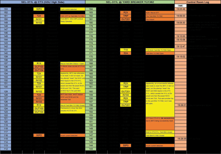
Figure 1: Sequence of Events Compiled from Numerical Line Current Differential Relays
SEQUENCE OF EVENTS
Figure 2 shows the overall one-line diagram for the power system.
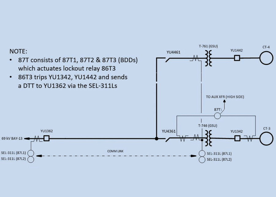
Figure 2: One Line Diagram
Figure 3a through Figure 3e illustrate the sequence of events leading up to the restoration of the adjacent generator.
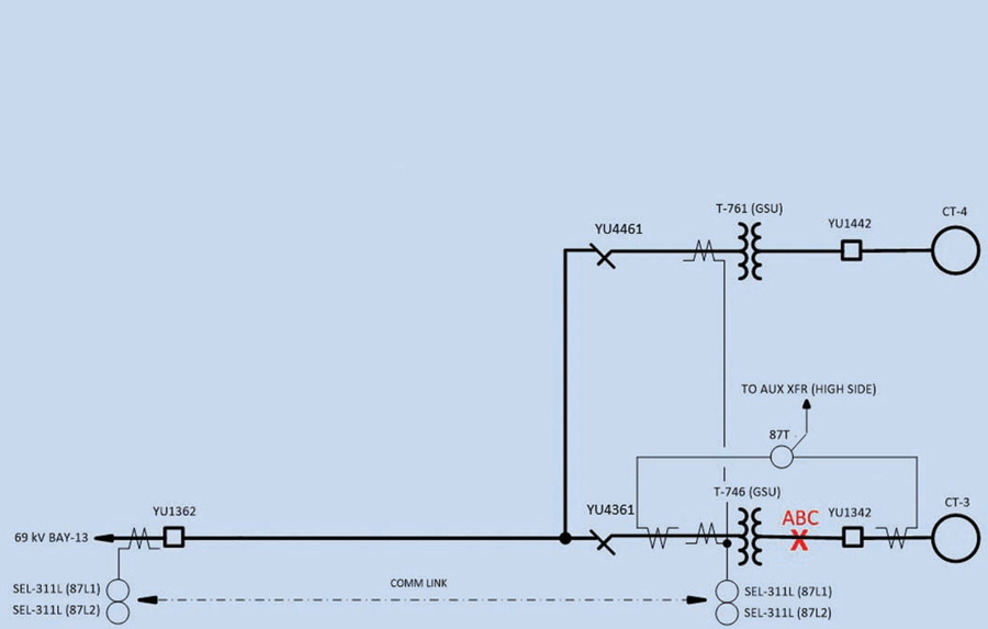
Figure 3a: Three-Phase Bus Fault on GSU Low Side
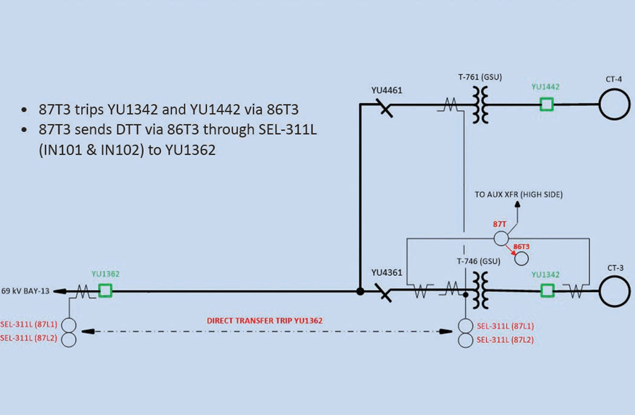
Figure 3b: Direct Transfer Trip to Switchyard Breaker via Numerical Line Current Differential Relays
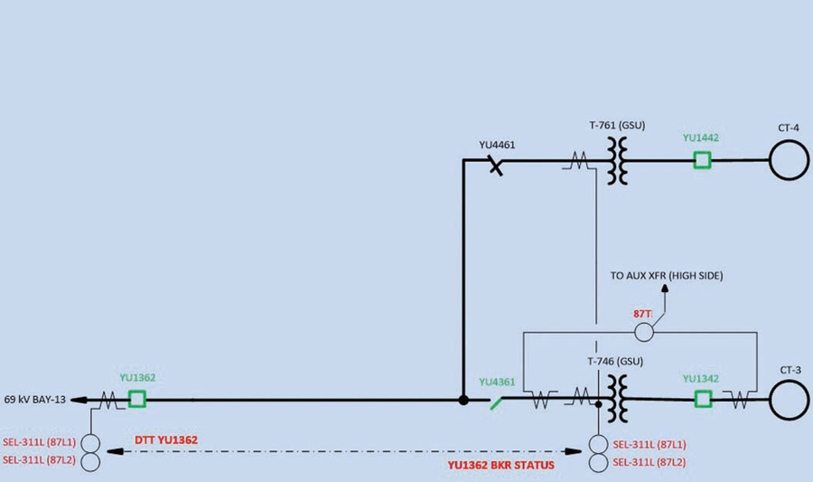
Figure 3c: Disconnect on High Side of Adjacent GSU Opened
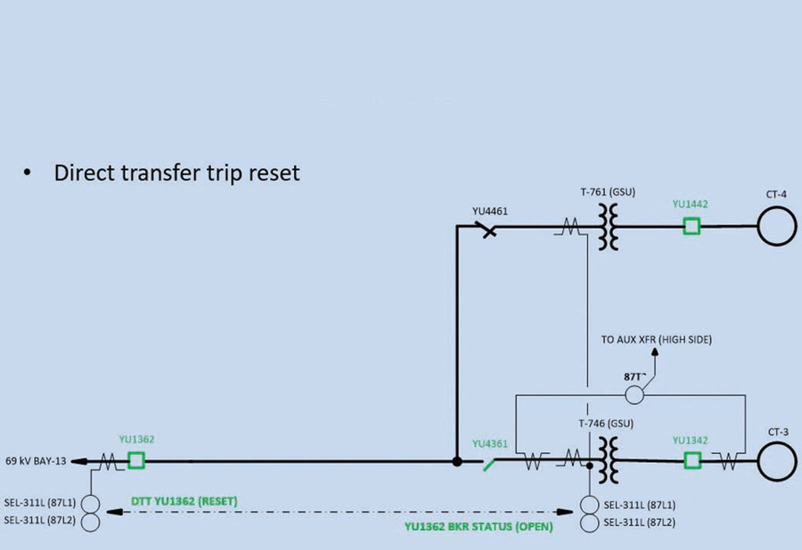
Figure 3d: Lockout Relay Reset
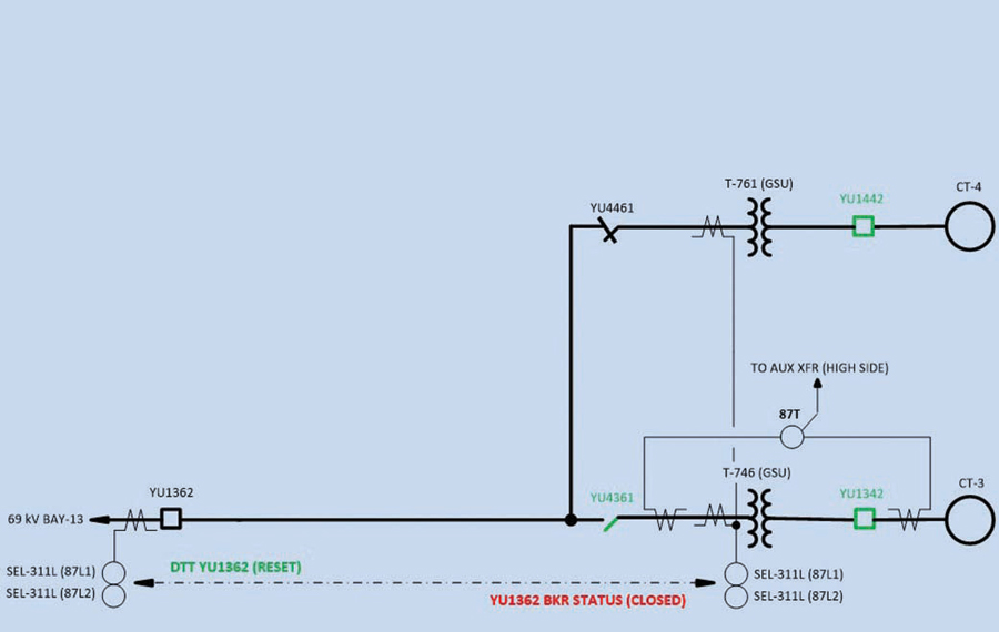
Figure 3e: Switchyard Breaker Closed
The adjacent generator was brought back on gear at time equal to 19:28:35.
Figure 4 shows the inrush current measured by the numerical line current differential relays following closing the switchyard breaker.
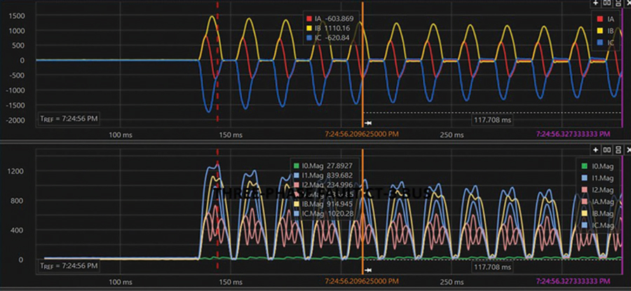
Figure 4: Inrush Current Following Closing Switchyard Breaker
Conclusion
Advantages offered by numerical protection relays include:
- Event reporting
- Event summary reports
- Event history reports
- Event reports
- Sequential events recorder report
This article demonstrates how the event recording taken from the numerical line current differential relays protecting the line to the faulted GSU can be used to verify that the overall system protection operated properly.
 Steve Turner is in charge of system protection for the Fossil Generation Department at Arizona Public Service Company in Phoenix. After working with Beckwith Electric Company, Inc. for 10 years, Steve spent two years as a consultant in San Diego. His previous experience includes positions as an Application Engineer at GEC Alstom and in the international market for SEL focusing on transmission line protection applications. Steve also worked for Duke Energy (formerly Progress Energy), where he developed the first patent for double-ended fault location on overhead high-voltage transmission lines and was in charge of all maintenance standards in the transmission department for protective relaying. Steve has BSEE and MSEE degrees from Virginia Tech University. He has presented at numerous conferences including Georgia Tech Protective Relay Conference, Western Protective Relay Conference, ECNE, and Doble User Groups, as well as various international conferences. Steve is a senior member of IEEE and a member of the IEEE PSRC.