

Power quality investigations commonly begin with events such as equipment trips, overheated transformers, unexplained relay trips, or electric machine failure. We measure voltage and current and evaluate harmonics, unbalance, transients, power factor, and other conditions to determine their effects on equipment. That work remains necessary. Changes in generation, distribution, storage, and power electronics require us to examine more of the connected system to understand how these technologies affect the electrical network as a whole.
A battery energy storage system (BESS) illustrates the challenge. Charging draws active power; discharging supplies it. Its power electronics may also supply or absorb reactive power to support voltage or respond to torsional or frequency oscillations. Each condition changes current through the converter, transformer, and connecting circuits. The response depends on equipment capability, control settings, and conditions of the connection.
Similar interactions occur across wind and solar plants, industrial facilities, data centers, and coordinated distributed resources. Equipment responds to the electrical system while influencing it—the relationship described by this article. Testing personnel must connect that behavior with equipment condition and reliable operation, and be able to identify conditions that existed when investigating an event.
CONSIDER THE COMPLETE PLANT
An inverter-based resource (IBR) interfaces generation or storage with the AC system through power electronics. Examples include solar photovoltaic generation, BESS, and many wind turbine designs. A distributed energy resource (DER) is connected within a distribution system and may use inverter-based or rotating-machine technology. These terms may overlap, but they describe different characteristics.
A virtual power plant (VPP) coordinates geographically distributed generation, storage, and controllable demand. Resources can occupy different feeders and may not necessarily be one electrical plant. High-voltage direct current (HVDC) systems transfer power through DC circuits and converters and inverters. For a two-terminal link, one AC terminal receives active power while the other delivers it, subject to losses. Converter and inverter technologies, controls, filters, and network conditions determine the local response.
IBR and DER are often discussed as individual generators. However, the grid sees the combined installation: transformers, collector circuits, auxiliaries, reactive compensation, protection, and controls. The plant may supply or consume active power, and supply or absorb reactive power. An inverter specification cannot establish the completed plant’s behavior as generation, load, or both. Figure 1 illustrates the shared network.
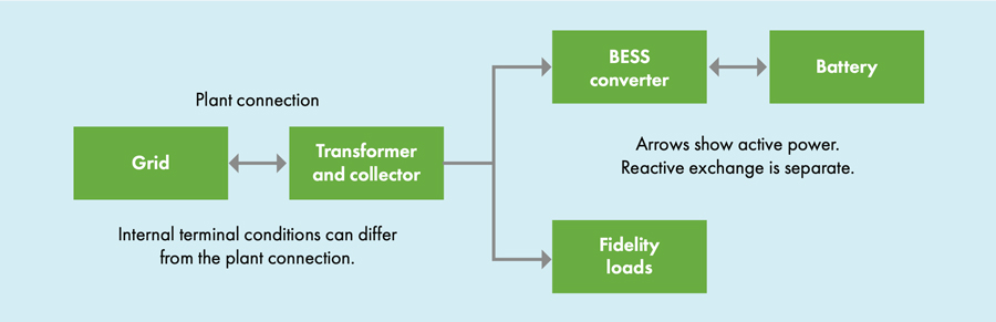
After sunset, a solar plant’s auxiliaries can still consume electricity, energized collector circuits can affect reactive exchange, and a co-located BESS may charge. Measurements and models must represent that operating condition, even though the site is called a generating plant.
Thousands of individually compliant devices may respond to one dispatch signal or voltage disturbance. Their combined power change can affect feeder voltage. VPP operators need resource locations, local constraints, timing, and communications status alongside aggregate megawatts. Verify that local controls and limits take precedence as intended when an aggregate command cannot be delivered.
THE INFORMATION GAP BECOMES A TESTING PROBLEM
Incomplete original equipment manufacturer (OEM) control documentation and incomplete design and construction records leave owners, testing personnel, and grid operators without a reliable description of the plant. Records should identify available and enabled functions, limits, control priorities, and the installed configuration. Factory capability, an entered setting, and verified plant response are different things.
These gaps affect planning and operating models. Omitted functions, assumed settings, unavailable equipment, or construction changes can separate predictions from field performance. A mathematically correct model may describe a plant that was never built in that configuration.
The consequences include errors in expected voltage regulation, reactive-power capability, disturbance response, and power exchange with the local and bulk grids. The joint North American Electric Reliability Corporation (NERC) and Texas Reliable Entity (RE) investigation of the 2022 Odessa disturbance identified the importance of models reflecting actual modes, controls, settings, and protection. This makes documentation quality an operational issue, not simply a project closeout task.
Independent testing helps verify that what was specified, installed, configured, and demonstrated aligns. Proprietary code need not appear in routine reports, but functional behavior, limits, and model information must support performance assessment. Record unknown behavior as an unresolved limitation.
ACCEPTANCE AND COMMISSIONING HAVE COMPLEMENTARY ROLES
NETA’s emphasis on independent testing and consensus standards is directly relevant to these installations. ANSI/NETA ATS-2025 addresses suitability for initial energization and includes sections for BESS and solar photovoltaic systems. ANSI/NETA ECS-2024 addresses commissioning and system performance verification against the owner’s project requirements and basis of design. These activities provide complementary evidence about equipment condition and the completed installation.
Inspect the installation, evaluate insulation and connections, verify instrument transformers, test breakers and relays, and confirm wiring and interlocks using applicable procedures. Converter controls cannot compensate for defective terminations or incorrectly connected current transformers. Correct ratios, polarity, and phase identification underpin power and protection measurements.
Then evaluate the assembled system. A relay may pass individually while a plant controller initiates an unexpected response. A converter may meet factory specifications while the plant cannot deliver the required reactive power at the interconnection. Identify those interfaces and assign responsibility for evaluating them.
Field testing organizations need not redesign the plant or perform every stability study. They must communicate exceptions to responsible engineers and operators. Tie acceptance to the equipment, operating condition, and requirement evaluated.
BESS MUST BE TESTED ACROSS OPERATING MODES
A BESS includes batteries, power conversion, battery management, controls, protection, and supporting electrical equipment. Its AC behavior changes with charging, discharging, reactive duty, and transitions. Testing at one steady discharge point cannot establish performance across that range.
For a 10 MVA converter at nominal voltage, assume balanced fundamental-frequency operation and neglect distortion. The idealized limit P² + Q² ≤ S_rated² leaves 6 Mvar at 8 MW. P is active power, Q reactive power, and S_rated the assumed apparent-power rating. At 10 MW, no reactive margin remains. Figure 2 shows this shared capacity, not an OEM capability curve. Actual limits depend on voltage, temperature, DC conditions, and control priorities. Transformers and collector circuits further affect plant capability.
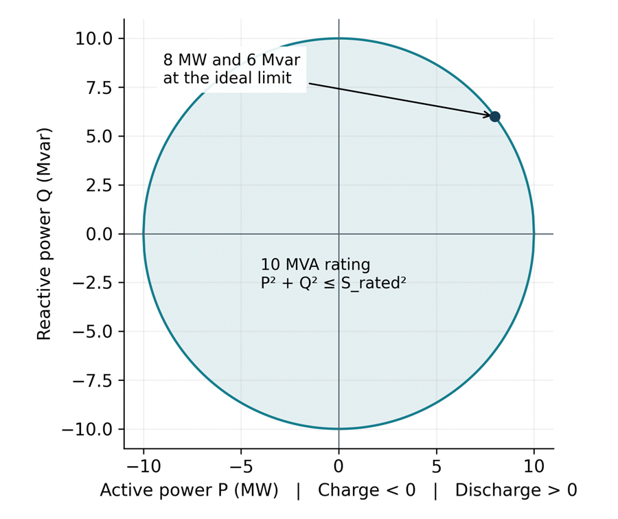
When a voltage disturbance calls for reactive current near the converter’s current limit, what governs allocation? Does active power decrease? Does reactive current take priority, or do battery controls restrict the response? Document and verify these functions through appropriate tests or studies. Megawatts alone are insufficient.
State of charge limits sustained response even when instantaneous power capability is adequate. Temperature and unavailable battery racks impose further restrictions. Connect AC measurements with battery state, commands, active limits, and equipment availability.
Test representative charging, discharging, low-output, and permitted reactive conditions. Near zero active power, reactive current can still produce losses. Evaluate transformer temperature against root-mean-square (RMS) current, reactive duty, ambient conditions, and loading history. Reversed active-power flow alone does not establish an abnormal condition.
Consider an illustrative trip: a voltage sag precedes rising reactive current, falling active power, and a converter alarm. Investigate current allocation and converter limits. A battery-management restriction preceding the AC change suggests a different sequence. Neither proves root cause; compare time-aligned records with enabled logic.
CONTROLS AND PROTECTION DETERMINE THE RESPONSE
Grid-following controls generally synchronize to an existing voltage waveform and regulate current or power relative to it. Grid-forming controls establish an internal voltage reference and regulate their interaction with the network. The distinction describes dynamic behavior, not simply the energy source. The NREL grid-forming research roadmap discusses both the potential support and the integration challenges.
A grid-forming label does not establish unlimited fault current, islanding, or black start. These depend on equipment, auxiliaries, controls, protection, and the operating envelope. Verify the functions purchased and enabled.
Network impedance matters because converter current changes terminal voltage and therefore controller response. Multiple devices interact through that network. Short-circuit ratio compares available short-circuit capacity with resource rating; state the rating convention used. A weaker connection generally experiences greater voltage change for a given current change. This indicator is neither a complete stability assessment nor synchronous-machine short-circuit ratio.
Fast interactions may require electromagnetic transient (EMT) modeling, coordinated with field measurements. Protection must be represented as well as normal control behavior. Simply relaxing a trip setting to improve ride-through can expose equipment to conditions beyond its capability. The engineering review must reconcile system requirements, equipment limits, protection coordination, and the installed configuration.
PLANT PERFORMANCE CAN IMPOSE INTERNAL STRESSES
Grid requirements may apply at the high-voltage connection while equipment ratings apply at individual terminals. Transformer impedance, collector cables, compensation, and auxiliary demand separate those locations. Meeting the interconnection requirement does not establish acceptable internal component loading.
Synchronous plants also require evaluation of the generators, excitation systems, limiters, step-up transformers, and auxiliaries. Starting, load cycling, and reactive duty can increase thermal and mechanical stress. Elevated voltage relative to frequency increases magnetic flux and can cause heating. Evaluate changed duties against design and present condition.
A data center presents a related concern. Transition of an uninterruptible power supply (UPS) to battery operation can preserve computing while abruptly reducing utility demand. Restoration and recharge create another operating condition. NERC identifies voltage sensitivity and control interactions as large-load concerns. Retain service-entrance measurements alongside UPS status and internal records.
CONNECT POWER QUALITY WITH EQUIPMENT CONDITION
Harmonics, unbalance, transients, and power factor remain useful evidence. Displacement power factor describes the fundamental voltage-current relationship, while true power factor relates active to apparent power and includes distortion effects. Retain harmonic current in amperes as well as percentages; a high percentage at low fundamental current does not necessarily mean a large harmonic burden.
Voltage distortion depends on harmonic currents, existing background distortion, and network impedance. Capacitors, cables, transformers, and filters alter the frequency response. A compensation change can reduce one problem while increasing another. A spectral peak identifies frequency content, but additional evidence is needed to distinguish resonance, switching effects, and control oscillation.
For example, a capacitor stage and network inductance can create a frequency at which distortion is amplified. Changing the stage or feeder configuration changes that frequency. Compare spectra across those configurations and use an impedance study where warranted. A compliant steady-state harmonic result in one configuration does not establish acceptable behavior across all configurations.
Our IEEE, NETA, wind power, and CIGRE work connect electrical signatures with operating conditions and component histories. Corroborate diagnoses against the connected circuit. A signature from one design should not automatically become a universal alarm.
For BESS transformers, combine electrical measurements with thermal inspection, dissolved gas analysis (DGA), fluid type, and loading history. DER transformer DGA standards development emphasizes application-specific information. An abnormal gas result warrants investigation but does not independently identify inverter harmonics as the cause.
CAPTURE THE EVENT AT THE RIGHT LOCATIONS
Routine supervisory control and data acquisition (SCADA) trends establish operating context but may miss a disturbance lasting only a few cycles. Waveform records, relay oscillography, controller logs, and battery-management records provide complementary information when their timestamps can be related. Table 1 shows the evidence needed to reconstruct the sequence.
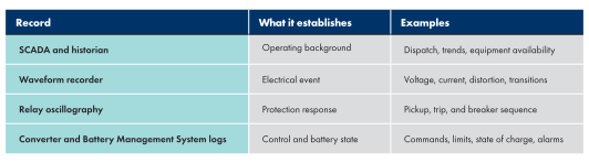
Use the one-line diagram and symptom to select interconnection and internal measurement points. Account for transformer connections, transducers, and phase relationships; confirm scaling and time alignment. Where practical, retain synchronized voltage and current on both sides of the equipment under investigation.
Choose sampling rate, record length, filtering, and triggering to match the phenomenon. Longer records improve frequency resolution and capture slower oscillations; faster sampling supports higher-frequency investigation. The transducers and complete acquisition chain must have suitable bandwidth. IEC 61000-4-30:2025 includes methods for conducted emissions through 150 kHz in its annexes. A high sampling rate alone does not establish measurement accuracy over that range.
Use approved procedures and appropriately rated equipment. Evaluate disturbances through suitable simulation, laboratory or controlled functional tests, and retained field events. Obtain evidence without creating uncontrolled disturbances on operating installations.
CLOSE THE GAP BETWEEN STUDIES AND FIELD PERFORMANCE
The European Network of Transmission System Operators for Electricity (ENTSO-E) investigation of the Iberian blackout on April 28, 2025, identified interacting factors involving oscillations, voltage and reactive power control, output reductions, and generator disconnections. Its March 2026 findings emphasized the need for improved monitoring, coordination, and data exchange. The lesson for testing is the importance of connecting local behavior with the wider system response.
IEEE 1547-2018 addresses DER interconnection with distribution electric power systems; IEEE 1547.1-2020 specifies associated conformance tests and evaluations. IEEE 2800-2022 addresses transmission-connected IBR, and IEEE 2800.2-2026 provides recommended practices for verifying plant-level conformity. Determine the applicable edition, reference point, interconnection agreement, and project requirements before selecting acceptance criteria. These documents complement equipment testing; they do not make every equipment terminal an interconnection compliance point.
Retain each function’s command, mode, settings, measured response, criterion, and disposition of exceptions. Table 2 connects participants with evidence. Compare the installed response with the study, as responsible engineers must resolve discrepancies in equipment, configuration, models, or requirements.
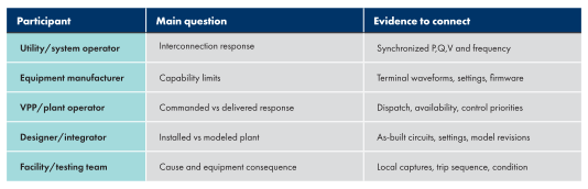
After correction, repeat relevant tests and assess other operating modes. Preserve the final configuration and update models where applicable. Use that maintenance baseline to distinguish deterioration from changed duty or controls. Firmware, compensation, and dispatch changes can justify renewed verification.
Evolving guidance must connect operating experience with interpretation. Reports should explain what was demonstrated, what remains unresolved, and what action follows. A pass/fail entry without an operating context offers little help during the next disturbance.
CONCLUSION
Generation, distributed resources, and storage change the duties that electrical testing personnel must evaluate. The complete plant affects local and bulk grids as generation, load, and a source or sink of reactive power. Individual equipment capability explains only part of that response.
Incomplete control and construction information affect commissioning, maintenance, grid operation, and models. Independent testing connects design with installed performance. Retain sound equipment testing, verify system interfaces, and carry findings into corrective action and maintenance to support safer, more reliable equipment.
REFERENCES
- Long, A., R. Long, and N. Mims Frick. Virtual Power Plants: Insights, Profiles and Inventory. Lawrence Berkeley National Laboratory, 2025.
- North American Electric Reliability Corporation and Texas Reliability Entity. 2022 Odessa Disturbance: Texas Event June 4, 2022. December 2022.
- ANSI/NETA ATS-2025. Standard for Acceptance Testing Specifications for Electrical Power Equipment and Systems.
- ANSI/NETA ECS-2024. Standard for Electrical Commissioning Specifications for Electrical Power Equipment and Systems.
- Lin, Y., et al. Research Roadmap on Grid-Forming Inverters. NREL/TP-5D00-73476, 2020.
- North American Electric Reliability Corporation. Characteristics and Risks of Emerging Large Loads. Large Loads Task Force White Paper. July 2025.
- Penrose, H. W. “Evaluation of DFIG Wind Turbine Generator and Transformer Conditions with Electrical Signature Analysis.” IEEE Electrical Insulation Conference, 2022.
- Penrose, H. W. “Electrical Signature Analysis of Oil- and Dry-Type Transformers.” NETA World, Summer 2024.
- Penrose, H. W. “The Scope and Application of Electrical Signature Analysis in Windpower.” CBM CONNECT, December 13, 2023.
- Penrose, H. W. “Practical Applications of Electrical and Current Signature Analysis in DFIG Wind Generator and Powertrain Reliability Evaluation.” CIGRE International Symposium, Montréal, Québec, Canada, Sept. 29–Oct. 3, 2025.
- Penrose, H. W. “Distributed Energy Transformer Dissolved Gas Analysis Standards Development.” Emerging Technologies, a NETA World journal special publication, Fall 2025.
- IEC 61000-4-30:2025. Electromagnetic compatibility (EMC) – Part 4-30: Testing and measurement techniques – Power quality measurement methods. Corrected version, July 2026.
- European Network of Transmission System Operators for Electricity. Final Report on the Grid Incident in Spain and Portugal on 28 April 2025. March 20, 2026.
- IEEE. IEEE Std. 1547-2018, Interconnection and Interoperability of Distributed Energy Resources with Associated Electric Power Systems Interfaces.
- IEEE. IEEE Std. 1547.1-2020, IEEE Standard Conformance Test Procedures for Equipment Interconnecting Distributed Energy Resources with Electric Power Systems and Associated Interfaces.
- IEEE. IEEE Std. 2800-2022. Interconnection and Interoperability of Inverter-Based Resources (IBRs) Interconnecting with Associated Transmission Electric Power Systems.
- IEEE. IEEE Std. 2800.2-2026. Recommended Practice for Test and Verification Procedures for Inverter-Based Resources Interconnecting with Bulk Power Systems.
- Penrose, H. W. “The Evolution of Standards to Support Advancing Grid Technologies.” NETA World, Fall 2026.

Howard W. Penrose is the president of MotorDoc LLC, a veteran-owned small business, and Founder/CEO of Human Reliability Intelligence Labs. He is Chair of the CIGRE-USNC A1 Study Group (power generation), Chair of IEEE 1415, Chair of ACP transformer DGA standards, convenor of CIGRE A1.78, and serves in IEEE, ACP, and CIGRE standards and related committees. Penrose also serves on the IEEE PES Grid Code committee responsible for the power generation section and is a leading researcher in supra-harmonic impacts.