

Originally, instrument transformers, in addition to providing an accurate representation of primary currents at a lower level, had to be able to power electromechanical relays with enough energy to operate them reliably. When microprocessor relays came along, that high power transfer was no longer necessary, yet the industry kept the same types of instrument transformers, because it was simpler to replace just the relay and keep the primary sensors in place. Today, the industry is transitioning from bulky, iron-core inductive transformers to low-power electronic sensors which leverage modern measurement principles to deliver precise signals for digital protective relays [1], [2].
Doing away with the heavy iron-core assemblies that historically dominated substation hardware, these low-power electronic units free designers to produce significantly more compact switchgear layouts while also reducing the safety hazards that come with working near energized high-voltage conductors [3]. By eliminating magnetic saturation and minimizing the potential for high-voltage open-circuit hazards, these sensors offer enhanced operational safety and increased flexibility in high-density substation environments [4].
Furthermore, by producing millivolt-level analog outputs, these devices facilitate direct integration with intelligent electronic devices, streamlining the transition toward digitized substation architectures in accordance with IEC standards [5], [6]. This evolution toward linear, air-core technology—often utilizing the Rogowski coil principle—removes the constraints of ferromagnetic core saturation, allowing for consistent measurement accuracy across a broad dynamic range of primary currents [7].
Some names used for these devices include non-conventional instrument transformers (NCIT), electronic transformers, low-power instrument transformer (LPIT), low-power current transformer (LPCT), and low-energy analog (LEA) interfaces or sensors. These sensors are specifically engineered to interface with modern relays that comply with IEEE Std. C37.92, Low-Energy Analog Interfaces between Protective Relays and Power System Signal Sources, IEC 61869-10, and IEC 61869-11 standards[4].
PRINCIPLES OF SENSOR OPERATION
LPITs rely on diverse physical phenomena to translate high-voltage/current power system quantities into small-signal representations suitable for digital input.
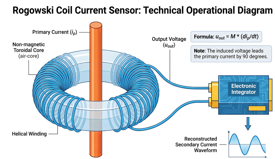
A popular type of current-sensing device is the Rogowski coil, which produces an output voltage proportional to the time derivative of the primary conductor’s current through mutual induction. Because the coil lacks a magnetic core, it maintains high linearity across a wide range of currents without the risk of saturation, necessitating an electronic integrator to reconstruct the original current waveform [8].
With Rogowski coils, the voltage output has a 90-degree phase shift relative to the current it measures. This is corrected by integration performed by active or passive circuitry within the sensor head or the relay input stage, which restores the phase relationship. This 90-degree phase shift can affect the testing and needs to be compensated for by the test set when producing signals for the current channels in the relays.
LOW-POWER CURRENT TRANSFORMERS
LPCTs utilize a low-burden magnetic core design that operates in a linear region to provide a scaled-down analog representation of the primary current, effectively minimizing the saturation risks associated with traditional, high-burden secondary windings. These types of current sensors use a burden resistor inserted in the secondary of a current transformer.
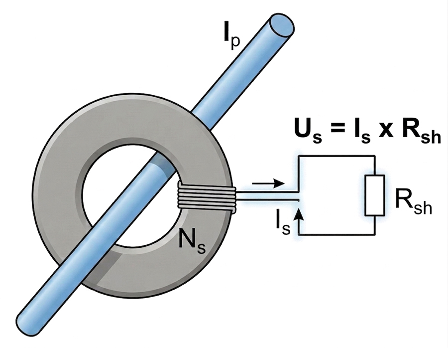
An iron-core LPCT, also known as LOPO [9], is fundamentally different from a Rogowski coil because it utilizes a ferromagnetic circuit to measure current. Its design includes:
- Ferromagnetic Iron Core. A small, high-precision iron core provides magnetic coupling between the primary and secondary.
- Secondary Winding. The secondary wire is wound around this core with minimized losses.
- Integrated Shunt Resistor (Rsh). This is the defining feature of the sensor. The secondary winding is internally terminated by a precision resistor, which acts as a current-to-voltage converter.
- Proportional Output Signal. The voltage measured across the shunt resistor (Us) serves as the output signal. Because it is directly proportional to the primary current (Ip), the output waveform matches the primary waveform perfectly.
Comparison to Rogowski coils
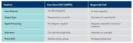
While both are considered LPCTs under the IEC 61869-10 standard, they operate on different mathematical principles, as seen in Table 1.
Field Advantages
- Simplified Testing. Since the output is proportional and lacks a 90-degree phase shift, specialized test sets do not need to apply complex derivative math to simulate the primary current.
- Standardization. These sensors provide a standardized low-voltage analog output (often 22.5 mV, 150 mV, or 225 mV) that is directly compatible with modern relays featuring high-impedance inputs.
- Safety. Like all LPITs, the internal shunt resistor ensures there is no risk of hazardous high-voltage spikes if the secondary terminals are accidentally opened while the primary is energized
Optical current transformers are current sensors that operate on the Faraday effect, in which the plane of polarized light passing through an optical fiber is rotated by a magnetic field proportional to the primary current, enabling high-precision measurements without electromagnetic induction [10]. Optical current transformers are expensive, which limits their use to 115 kV and above systems [3].
Resistive current sensors use a shunt resistor placed directly in the primary circuit, converting current into a proportional voltage via Ohm’s law, providing a high-precision, non-magnetic alternative for localized sensing [11].
All the current sensors mentioned above convert the current signal into an equivalent low-magnitude voltage signal, which is interpreted by the relay as a current input [12].

VOLTAGE SENSORS
Voltage sensing is typically achieved through capacitive divider networks that use a series of capacitors to reduce the high-voltage input to a safe, low-power level suitable for processing [13]. Other voltage-sensing devices use resistive dividers. These resistive voltage dividers operate by forming a simple voltage drop across high-impedance resistors, offering accuracy for steady-state measurements, though they may have transient performance limitations [14].
STANDARDIZED OUTPUT LEVELS FOR LOW-ENERGY ANALOG SENSORS
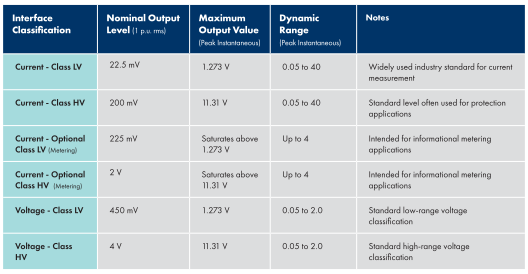
According to IEEE Std. C37.92-2023, LEA interfaces are standardized into different classes based on their nominal signals and the applications they serve. These nominal levels (1 p.u.) correspond to the rated primary rms value of current (In) or voltage (Vn) in the measured circuit.
Table 2 summarizes the common nominal levels, maximum output peak values, and dynamic ranges for current- and voltage-sensing systems.
Key Technical Considerations
- Dynamic Range. Current-sensing systems must accommodate a wide dynamic range to capture everything from low-load currents to high-magnitude faults. Voltage-sensing systems focus on a range around nominal system voltage, generally reaching up to twice the rated voltage.
- Optional Current Outputs. The optional 225 mV and 2 V outputs are specifically intended for informational metering applications where a smaller dynamic range (4 p.u.) is acceptable.
- Peak Value Calculation. The maximum instantaneous values are calculated based on the dynamic range and the peak factor (rms×dynamic range×2). For example, the maximum output for Class LV Current is 0.0225 V×40×2≈1.273 V.
- High-Voltage Divider Ratios. In specific applications such as pole-top reclosers, it is common to use a standardized 10,000:1 ratio to transform primary AC voltage to these lower LEA levels. Regardless of the ratio used, the standard ensures that the relay physically receives signals typically less than 11.31 V peak.
STANDARDIZED CONNECTOR INTERFACES FOR LPITS
Many relay manufacturers now offer dedicated LPIT-compatible inputs that follow IEEE C37.92 and IEC 61869 standards, facilitating seamless plug-and-play integration. An important difference between the use of LPIT and regular instrument transformers concerns the connections at the relay. Instead of using traditional terminal blocks with bolted connections, these sensors utilize specialized low-voltage connectors, such as RJ45 or bayonet-style locking interfaces, to ensure signal integrity and simplify field installation [15]. The backplane of an SEL 787 relay is shown in Figure 4 as an example where E and Z terminals have been replaced by RJ45 inputs for both voltages and currents.
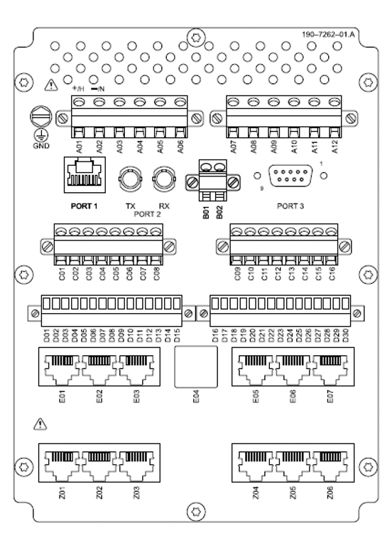
Although the most common type of connector used to interface LPITs with modern protection relays is the shielded RJ45 connector, they are not the only type of connector used. According to IEEE Std C37.92-2023, the preferred interface connectors are specifically the RJ45 type and the M12 type.
The specific characteristics and applications of these connectors are detailed below:
1. RJ45 Connectors
- Widespread Use: This is the industry-standard connector for most primary distribution applications and is used by major manufacturers.
- Physical Interface: Although these connectors are physically identical to standard Ethernet plugs, they are not Ethernet ports and carry point-to-point LEA signals.
- Cabling: They typically utilize shielded twisted-pair cables (minimum Cat 5E) to maintain signal integrity and ensure electromagnetic compatibility (EMC).
- Distance Limits: Standards such as IEC 61869 limit the use of RJ45 connectors to installations where the distance between the LPIT and the relay is less than 10 meters.
- Standardized Pinouts: Both IEEE C37.92 and IEC 61869-6 define specific pin assignments for these connectors to ensure multi-vendor interoperability. For example, a common pinout uses Pins 1 and 2 for current (LPCT) signals and Pins 7 and 8 for voltage (LPVT) signals.
2. M12 Connectors
- Construction: The M12 is an 8-way, shielded circular connector that often features a locking nut for secure attachment.
- Suitability: Like the RJ45, it is a preferred standard for LEA interfaces, particularly when ruggedness and shielding against environmental factors are required.
3. Legacy and Alternative Connector Types
While RJ45 and M12 are the modern standards, other connectors may be encountered:
- Twin-BNC: Some older or specialized IEDs utilize Twin-BNC connectors; adapters are available to convert these to the standard RJ45 interface.
- Ferrules: Certain fault-passage indicators or specific product versions may use simple wire ferrules for terminal-block connections rather than a modular plug.
- Terminal Blocks: For testing and commissioning, LPIT analog terminal blocks may be used to provide a classic secondary analog injection point.
Standardization of these connectors and their pinouts is critical for a “plug-and-play” system, allowing sensors from one manufacturer to be seamlessly integrated with relays from another.
Despite the IEEE C37.92 standard recommendations to integrate a voltage and a current channel in the same connector, some protection relay sensor inputs separate voltage and current channels into different input connectors.
ADVANTAGES OF USING LPITs
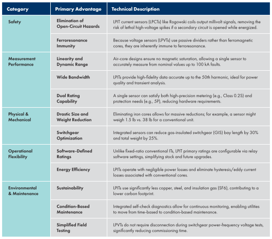
In general, LPITs offer significantly improved linearity and accuracy, while eliminating the risks of magnetic saturation and ferroresonance common in traditional iron-core inductive transformers [16]. Table 3 summarizes the advantages of using LPIT over conventional CT and VT.
CONCLUSION
LPITs are not new in the industry, but their use is increasing at a rapid pace due to factors such as flexibility, greater growth potential, increased pressure of digitalization in substations, lower price, and smaller footprint when compared with conventional instrument transformers.
REFERENCES
- Woo, G., S. Ko, and P. Park. “Practical Testing Approaches for LPIT in Digital Substations.” November 2025, 132–136. doi: 10.1109/gtdasia60461.2025.11313294.
- Mani, D. S., S. C. R. Thota, and A. J. González. “Field Testing Challenges and Innovations for LPITs in Relay Protection Systems.” March 2025, 1–10. doi: 10.1109/cfpr67343.2025.11013753.
- Menke, P., V. Skendzic, and N. Fischer. “Low-Power Instrument Transformers: Ideal Solution for Modern Data Centers, High-Density Industrial Applications, and Digital Secondary Systems.” Oct. 28, 2025.
- Mani, D., N. Wetterstrand, P. Menke, T. Neumeier, and F. Gatzen. “LPITs in High Voltage Switchgear and Field-testing of Relay Protection with LPIT Inputs.” 2024.
- Kim, D.-E., G.-Y. Lee, G.-S. Kil, and S.-W. Kim. “Trends in Measuring Instrument Transformers for Gas-Insulated Switchgears: A Review.” Energies 17, no. 8 (2024): 1846. doi: 10.3390/en17081846.
- Mingotti, A., C. Betti, L. Peretto, and R. Tinarelli. “Low-Power Instrument Transformers and Energy Meters: Opportunities and Obstacles.” IEEE Instrumentation & Measurement Magazine 26, no. 4 (2023): 44-48. doi: 10.1109/mim.2023.10146561.
- Napier, L., L. Cesky, and A. Pilarski. “Dynamic Protection System Performance Using Rogowski Coils.” Sep. 17, 2024.
- Poncelas, O., J. R. García, J. Cusidó, J. A. Ortega, and L. Romeral. “Motor Fault Detection Using a Rogowski Sensor Without an Integrator.” IEEE Transactions on Industrial Electronics 56, no. 10 (2009): 4062–4070. doi: 10.1109/tie.2009.2025715.
- Luescher, R., et al. “LPIT Applications in HV Gas Insulated Switchgear.” Sep. 2020. doi: 978-2-85873-519-8.
- Cease, T. W. and P. Johnston. “A Magneto-Optic Current Transducer.” IEEE Transactions on Power Delivery 5, no. 2 (1990): 548–55. doi: 10.1109/61.53056.
- Sun, H., S. Huang, and L. Peng. “High-Current Sensing Technology for Transparent Power Grids: A Review.” IEEE Open Journal of the Industrial Electronics Society 5 (2024): 326–58. doi: 10.1109/ojies.2024.3387432.
- Milovac, P., J. Xavier, L. Holloway, S. Davidovich, and C. Zheng. “Practical Aspects of Designing Safe and Compact MV Switchgear Using ‘Air Core CT’, ‘Resistor Voltage Divider VT,’ and Modern Intelligent Microprocessor Relays.” March 2021, 1-8. doi: 10.1109/cpre48231.2021.9429853.
- Mingotti, A., F. Costa, G. Pasini, L. Peretto, and R. Tinarelli. “Modeling Capacitive Low-Power Voltage Transformer Behavior over Temperature and Frequency.” Sensors 21, no. 5 (2021): 1719. doi: 10.3390/s21051719.
- Boggs, S. A., G. J. FitzPatrick, and J. Kuang. “Transient Errors in a Precision Resistive Divider.” Paper presented at the IEEE International Symposium on Electrical Insulation, Montreal, Canada, June 16-19, 1996. doi: 10.1109/elinsl.1996.549387.
- IEEE Std. C37.92-2023, Standard for Low-Energy Analog Interfaces between Protective Relays and Power System Signal Sources. Feb. 15, 2023. doi: 10.1109/ieeestd.2023.10106648.
- Majer, K., V. Prokop, and M. Celko. “Smart Medium Voltage Switchgear with LPITs and IEC 61850—Experiences after 10 years and the Next Evolution.” IET Conference Proceedings 2025, no. 14 (2025): 2042–46. doi: 10.1049/icp.2025.1991.

Abel González Gómez is the Power Protection Team Lead of the North American Technical Support Group (TSG) at Doble-Megger. His focus has been on relay testing, developing relay test routines, and providing training and application support for relay testing products. With 30 years of experience in electrical engineering, González has published numerous papers and technical articles and has presented them at various technical conferences. A member of IEEE, his main area of interest is the influence of IBR on the protection and control of electric power systems.

Jacob Loyd is a Relay Applications Engineer with Doble-Megger’s TSG group. His responsibilities at include providing technical support and training on relay and instrument transformer test sets. Previously, he spent 16 years in the nuclear power generation industry, with over a decade in electrical maintenance, working on everything from large power transformers to motor control circuits, before transitioning full-time to the protective relaying and controls group, helping with the transition from older electromechanical relaying to modern microprocessor-based solutions.

Dhanabal Mani is Director of Relay Software Development at Doble-Megger. He led the commissioning of India’s groundbreaking 400 kV IEC 61850 substation in Madhya Pradesh while working as the lead commissioning engineer at ABB India Ltd. Dhanabal also worked as an R&D engineer at ABB Ltd in Sweden, developing relay applications. With over 22 years of experience in protective relaying, he has published numerous articles and presented at prestigious international conferences, highlighting his significant contributions to the field.