

Very-low-frequency (VLF) withstand testing is a widely accepted method for commissioning and acceptance testing of newly installed medium-voltage cable systems. Many specifications require a one-hour VLF withstand test at elevated voltage levels to demonstrate the integrity of the installed cable system before energization.
However, a simple pass-fail withstand test provides limited information about the condition of a cable system that survives the test beyond the obvious, that the cable can withstand the overpotential. It does not, by itself, identify or locate partial discharge (PD) activity or the insulation defects associated with that activity that may be present during the test. Questions also remain regarding the effect of prolonged elevated-voltage exposure on cable accessories, particularly when partial discharge initiates.
CABLE ACCESSORIES AND ELEVATED-VOLTAGE STRESS
A medium-voltage cable system includes more than the cable insulation itself. Terminations, joints, and separable connectors are often among the most vulnerable components of a medium-voltage cable installation. Field experience and laboratory testing have shown that some accessories may begin exhibiting measurable PD at voltage levels below those used during acceptance withstand testing.
When PD occurs within voids, interfaces, contamination sites, or stress-control defects, localized erosion and electrical treeing may develop. The engineering concern is therefore not simply whether an accessory survives an acceptance test, but whether prolonged exposure above its PD inception level may initiate or accelerate degradation that would not otherwise occur under normal operating conditions.
WITHSTAND TESTING AND DIAGNOSTIC TESTING
A withstand test answers an important question: Did the insulation system survive the specified voltage for the prescribed duration? Diagnostic PD testing asks a different set of questions: Is discharge present? At what voltage does it begin? How large is the response? And where is it located?
Damped AC (DAC) PD testing applies a limited number of resonant voltage cycles while simultaneously evaluating the system for PD activity. It should not be viewed as a direct replacement for specification-required acceptance testing. Rather, it can provide diagnostic information regarding cable-system condition and the location of discharge activity while limiting prolonged exposure to elevated stress.
FIELD CASE STUDY
In one case study, four three-phase circuits were evaluated, and three of 24 (12.5%) individual phase terminations exhibited localized PD activity. The 12.5% finding applies only to this limited field sample and is not intended as an estimate of broader prevalence.
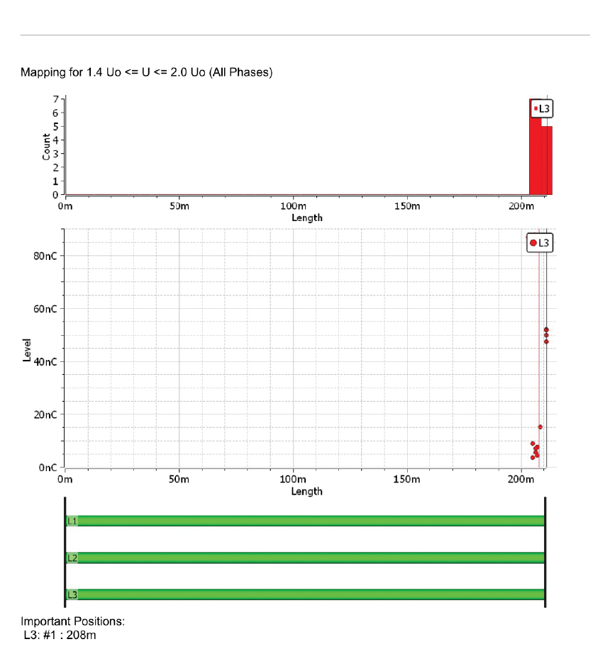
The most severe indication was localized to the far-end L3 termination of a 211 m circuit (Figure 1). Partial discharge was evident by 1.3 U0, with approximately 10 nC measured at or below 1.3 U0 and approximately 50 nC during testing from 1.4 to 2.0 U0. The circuit did not satisfy the applicable acceptance criterion.
Before-and-After Verification
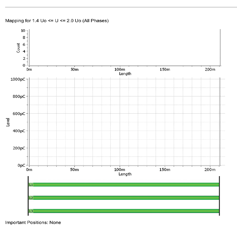
The original circuit was reported as failed. After the identified termination was remediated, the repeat DAC PD test found no significant PD positions on any phase (Figure 2). This before-and-after result links the original response to an actionable accessory location and verifies the effectiveness of the repair.
Additional Indications
Two additional circuits satisfied the applicable acceptance criteria, yet each exhibited far-end L1 PD in the 1.4–2.0 U₀ region: approximately 650 pC (Figure 3) and 1,600 pC (Figure 4). IEEE Std. 386-2016, Separable Insulated Connector Systems for Power Distribution Systems Rated 2.5 kV through 35 kV, requires separable connectors to have a minimum PD extinction voltage of approximately 1.3 U₀, with PD not exceeding 5 pC at that level. These observations show that connectors satisfying the applicable PD acceptance-test criteria may nevertheless exhibit substantial discharge activity when subjected to higher voltage stress.
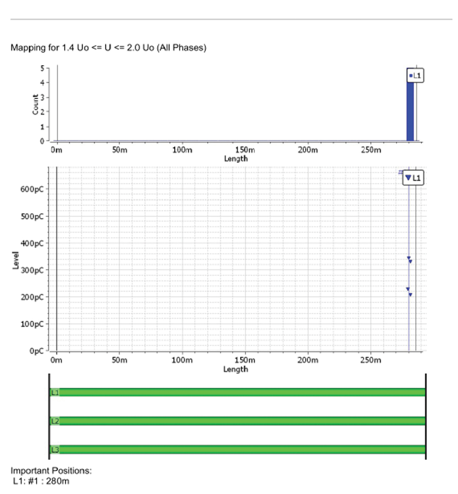
at the far-end L1 termination.
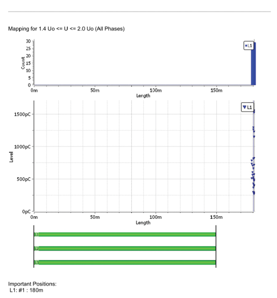
Figure 4: Another circuit showed approximately 1,600 pC
at the far-end L1 termination.
WHAT THE CASE DEMONSTRATES
The case demonstrates two different limitations of a pass/fail result. First, diagnostic PD testing identified and localized a severe termination defect, approaching 50 nC at elevated voltage, which could then be corrected and verified before energization. The field data do not establish when or whether that defect would have progressed to complete failure during a one-hour VLF withstand test. Had the circuit survived the prescribed test, however, the resulting pass indication alone would not have revealed the presence, location, or severity of the underlying PD activity.
Second, two additional terminations exhibited measurable PD at elevated voltage, even though the associated circuits met the acceptance criteria of the applicable testing specification. A successful withstand result, therefore, does not establish that an accessory remained electrically unaffected during the test. Where repetitive PD is present at elevated voltage, insulation degradation may occur, and an existing defect may be worsened even though the circuit ultimately survives the prescribed withstand period. The field data in this case do not quantify the amount of such degradation or establish that a particular accessory would have failed during the withstand test.
During a one-hour VLF withstand test at 2.0 U0, the affected accessories would remain exposed to elevated electrical stress for the prescribed withstand duration.
The value added by DAC PD testing in this case was therefore diagnostic in two important respects. For the most severe indication, it detected and localized the discharge before energization and confirmed that corrective work removed the identified response. For the two additional terminations, it identified lower-magnitude discharge activity at elevated voltage, even though those terminations satisfied the applicable acceptance criterion. Without diagnostic PD information, those conditions could have remained unidentified while the accessories were subjected to the prescribed elevated voltage withstand duration with partial discharge present.
REPETITION AND DISCHARGE SEVERITY
Once PD initiates at an existing termination defect or interface, continued elevated test voltage can sustain repetitive discharge activity. The field records establish that this can occur at elevated voltage in terminations acceptable at the applicable lower-voltage PD criterion; they do not establish a specific discharge count or quantify resulting damage. Apparent-charge magnitude can be difficult to visualize physically. Published laboratory investigations provide a useful perspective by showing that repetitive PD at substantially lower apparent-charge levels can produce observable insulation deterioration. In one reported insulation system, surface-discharge activity in approximately the 500 pC to 5 nC range was sufficient to continue degradation, with approximately 1 nC associated with permanent damage to cellulose fibers. Other controlled testing of solid epoxy insulation reported progressive deterioration under repetitive PD in approximately the 100 to 1,000 pC range.
These laboratory results are not directly transferable to the specific materials, interfaces, geometry, or electrical-stress distribution of a modern separable cable connector. Apparent charge alone also cannot be used to infer equivalent energy deposition or damage. The studies nevertheless provide a useful physical perspective: Repetitive discharge activity within or along polymeric insulation systems can produce progressive localized degradation, and the rate and significance of that degradation depend strongly on the defect, material, interface, electric-field distribution, and duration of exposure.The comparison is not intended to establish equivalent damage. Rather, it illustrates why repetitive discharge of this magnitude during prolonged elevated-voltage exposure should not be regarded simply as an insignificant electrical indication.
CONCLUSION
One-hour VLF withstand testing remains an established acceptance practice addressed by IEEE 400.2-2024, IEEE Guide for Field Testing of Shielded Power Cable Systems Using Very Low Frequency (VLF) (less than 1 Hz). However, the interaction between elevated acceptance-test voltages and accessory PD performance characteristics deserves careful consideration and further investigation.
The issue is not merely whether the cable system survives the acceptance test. The more important question is whether the test promotes the long-term reliability expected of the system. This raises a further question: When repetitive PD is present during prolonged elevated-voltage exposure, could the withstand test itself contribute to insulation degradation and become counterproductive to the long-term reliability it is intended to support? A successful withstand test alone may not fully characterize the condition or future performance of the cable system when PD is present during prolonged overvoltage exposure. Acceptance testing may therefore benefit from approaches that not only demonstrate insulation survival, but also provide insight into the presence, magnitude, and location of potentially damaging discharge activity. Diagnostic PD methods can add information beyond a simple pass-fail result, while preserving the primary objective of acceptance testing: placing reliable assets into long-term service.
REFERENCES
- IEEE. IEEE 400.2-2024, IEEE Guide for Field Testing of Shielded Power Cable Systems Using Very Low Frequency (VLF) (less than 1 Hz).
- IEEE. IEEE 400.3-2022, IEEE Guide for Partial Discharge Field Diagnostic Testing of Shielded Power Cable Systems.
- IEEE. IEEE 400.4-2015, IEEE Guide for Field Testing of Shielded Power Cable Systems Rated 5 kV and Above with Damped Alternating Current (DAC) Voltage.
- IEEE. IEEE Std. 386-2016, IEEE Standard for Separable Insulated Connector Systems for Power Distribution Systems Rated 2.5 kV through 35 kV.
- Sikorski, W. “Development of Acoustic Emission Sensor Optimized for Partial Discharge Monitoring in Power Transformers.” Sensors 19, no. 8 (2019): 1865. doi:10.3390/s19081865.
- Fujinami, H., T. Kawamoto, T. Takuma, and T. Okamoto. “Diagnostic Technique of Internal Deterioration in Epoxy Mold Spacer Used in Gas Insulated Switchgear (GIS).” Report T87082. Central Research Institute of Electric Power Industry, 1988.

Don Genutis is Vice President and General Manager of RESA Power Services. His career in electrical testing and maintenance spans more than four decades, including experience with partial discharge testing and diagnostics beginning with laboratory testing in the 1980s. His work has helped advance practical industry thinking on electrical testing, diagnostics, reliability, and the interpretation of field results. Genutis received a BS in electrical and electronics engineering from Carnegie Mellon University.