
Industrial electrical networks and utility grids share common elements: transformers, circuit breakers, protection relays, busbars, and insulated cables. Despite this, they differ profoundly in architecture, criticality, fault exposure, maintenance philosophy, and diagnostic strategies. A failure in an underground cable is more than the physical or functional loss of an electrical component; it can abruptly interrupt a continuous industrial process or leave thousands of consumers without power, resulting in massive financial losses and severe regulatory penalties. This duality necessitates engineering approaches that are carefully tailored to the operational realities of each facility.
The evolution of testing techniques has radically transformed the maintenance paradigm for these critical infrastructures. Traditional methods, such as DC insulation resistance measurement and DC withstand voltage testing, continue to play specific roles in preliminary verification but have shown significant limitations in detecting intrinsic defects associated with dielectric degradation. These tests have been progressively complemented by non-destructive techniques that determine the actual aging state of the insulating material and the location of defects: dissipation factor or tan delta (tan δ), partial-discharge (PD) detection and localization, time-domain reflectometry (TDR), and assessment of outer sheath integrity.
CIGRE, through its Technical Brochure TB 924 (2024), which is dedicated entirely to condition assessment and asset management of medium-voltage networks, consolidates the state of the art in these practices. The document explicitly identifies very low frequency (VLF tan δ) voltage testing, PD monitoring, damped AC (DAC) voltage testing, TDR, and outer sheath testing as priority tools for predictive diagnostic actions. CIGRE advocates that the selection of a methodology cannot be standardized generically; rather, it must result from a weighted assessment of the insulation type (XLPE, EPR, or PILC), service age, transient profile, and the circuit’s operational criticality.
TWO REALITIES: INDUSTRY AND ELECTRIC UTILITIES
The first fundamental distinction between the two environments lies in physical scale, power topology, and the primary mission of the electrical circuit. An industrial plant operates concentrated circuits within private geographical boundaries, where the integrity of the medium- or high-voltage supply is inextricably linked to the continuity of the manufacturing, refining, or mining production chain. In contrast, distribution utilities manage branched networks that extend for tens or hundreds of kilometers across urban and rural areas, subject to continuity metrics and regulatory penalties for widespread supply interruptions.
This infrastructural divergence dictates entirely different maintenance strategies. While the engineers in industry settings focus primarily on preventing a single production line stoppage, which can cost millions per hour of downtime, the utility balances maintenance costs against the management of regulatory and statistical risks across a vast array of circuits. Figure 1 summarizes the technical and operational distinctions between these two environments.
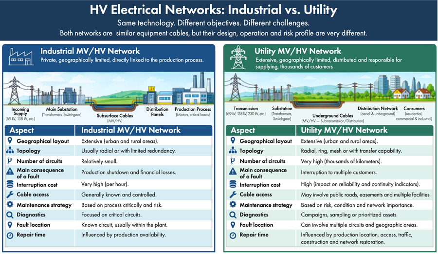
As shown, the number of assets in a manufacturing setting is limited, yet the severity of any incident is critical. Industrial risk analysis must quantify the direct financial impact of plant operational downtime, necessitating robust contingency plans and predictive maintenance routines focused on maintaining operational availability.
Conversely, for utility companies, treating the asset fleet uniformly is unfeasible. Management must process analytical variables (such as insulation type, manufacturer, thermal loading regime, splice density, soil corrosivity, DEC/FEC reliability indices, and emergency switching capability) while aligning diagnostics with strategic asset management principles. In this context, the following ANSI/NETA standards establish the criteria for these activities: ANSI/NETA ATS-2025, Standard for Acceptance Testing Specifications for Electrical Power Equipment and Systems, specifies parameters for the acceptance and commissioning of new circuits, whereas ANSI/NETA MTS-2023, Standard for Maintenance Testing Specifications for Electrical Power Equipment and Systems, defines tolerances and mandatory tests for evaluating equipment in continuous service.
THE VULNERABILITY OF INSULATED CABLES
The greatest challenge for technical teams is that dielectric deterioration in insulated conductors occurs silently within the cable layers and their accessories. A medium- or high-voltage feeder can operate continuously under rated current and voltage conditions without externally measurable thermal changes or protection alarms, even as micro-cracks, treeing, or delamination progress within the polymeric material, eventually leading to a total loss of dielectric strength.
The agents triggering this degradation form a complex matrix of interrelated multifactor stresses. Key mechanisms include thermal aging caused by overloads or continuous thermal cycling; moisture ingress through punctured sheaths, inducing the formation of water trees (electrochemical treeing); internal PDs within microscopic voids; manufacturing imperfections; and mechanical damage resulting from excessive tension or improper bending during installation. Additional issues include continuity failures in semiconducting and metallic screens, galvanic corrosion of copper tapes or wires, degradation of the grounding system, and frequent accidental external damage from uncontrolled excavation and civil works along underground circuit routes.
Field studies and statistical analyses consistently indicate that the system’s weakest link is rarely the continuous conductor itself, but rather its joints and terminations. The field installation of cable accessories introduces human variability into the electrical system: imprecise cutting of semiconducting layers, contamination by conductive particles or moisture, incorrect positioning of the stress control element, and improper torque application at mechanical connections create points of severe local electric field gradients. CIGRE emphasizes that, despite the rigorous factory quality control mandated by product standards, the field assembly and connection process necessitates mandatory commissioning tests before the systems are handed over for energization.
TESTS WITH DIFFERENT OBJECTIVES: ACCEPTANCE, MAINTENANCE, AND DIAGNOSIS
A common misconception in underground cable management is the tendency to group testing methodologies under a single operational category, disregarding the specific technical purpose of each test procedure. To ensure system reliability and avoid unnecessary operational costs or accelerated insulation degradation during testing, industry guidelines categorize verification routines into three distinct areas: acceptance, periodic maintenance, and predictive dielectric integrity diagnostics.
Acceptance tests, suggested by ANSI/NETA ATS-2025 and IEEE 400.2-2024, Guide for Field Testing of Shielded Power Cable Systems Using Very Low Frequency (VLF) (less than 1 Hz), focus on accurately determining whether a newly installed cable, along with its splices and terminations, has been assembled according to design specifications and is ready for initial energization. This process aims to identify installation-related damage and accessory assembly defects by applying controlled overvoltage and supplementary dielectric strength tests prior to handing the asset over for commercial operation.
Meanwhile, periodic maintenance tests, structured according to ANSI/NETA MTS-2023, aim to verify that circuits in continuous service maintain the functional compliance required for ongoing operation. In this context, tracking historical data is fundamental: a single, isolated data point does not reveal the structure’s aging rate, whereas a comparative analysis of historical parameters allows for predicting when the system is approaching the end of its service life. Unlike pass/fail approaches, diagnostic tests aim to determine the level of insulation degradation, the defect phenomena present, and their physical locations along the cable. This specialized category encompasses techniques such as dissipation factor (tan δ), PD characterization, TDR, frequency-domain reflectometry (FDR), DAC voltage monitoring at VLF, and tests of outer metallic sheath integrity. While a withstand voltage test merely verifies whether the insulation withstands the applied electrical stress, predictive engineering diagnostics quantify the intrinsic condition of the insulation and enable preventive decision-making prior to catastrophic in-service failure.
MAIN DIAGNOSTIC TECHNIQUES: VLF, TAN DELTA, AND PD
The development of VLF voltage testing technology represented a fundamental evolutionary milestone in enabling field testing for shielded power cable systems. IEEE 400.2-2024 establishes the technical parameters for conducting tests at frequencies typically in the 0.1 Hz to 0.01 Hz range, covering everything from withstand tests to advanced integrated diagnostic measurements of dielectric losses. The basis of this technique relates to the cable’s capacitive charging current, represented by the expression:
Ic = 2π · f · C · V
Where the operational quantities are duly described by:
- Ic: System capacitive charging current, expressed in amperes (amp)
- f: Frequency of the sinusoidal waveform applied during the test, expressed in hertz (Hz)
- C: Total equivalent capacitance of the cable circuit under test, expressed in farads (F)
- V: RMS test voltage applied to the conductor, expressed in volts (V)
Since the magnitude of the charging current is directly proportional to the test frequency, reducing the excitation from 60 Hz to 0.1 Hz reduces the required current and the apparent power output of the source by a factor of 600. This frequency reduction enabled the development of more compact, lightweight equipment, thereby allowing testing of longer underground circuits at higher test voltages. In accordance with IEEE 400.2-2024, it is essential to distinguish between the VLF withstand test (pass/fail) and VLF diagnostics, the purpose of which is to assess the degree of insulation degradation.
In this context, tan delta (tan δ) diagnostics quantify dielectric losses due to conduction and polarization within the insulation system, expressed by the scalar relationship between the components of the total current:
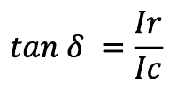
Whose physical components represent:
- Ir: The resistive component (active dielectric losses) of the current, in amperes (amp)
- Ic: The pure capacitive component of the reactive current, in amperes (amp)
In sound dielectric systems, resistive losses are low, resulting in tan δ values that are very low and stable across voltage increases. The presence of moisture, conductive voids, contamination, and widespread water treeing increases conductivity and dielectric loss, significantly raising the dissipation factor and the variation in tan δ between applied voltage levels (tip-up). The tan δ test reflects the overall condition of the insulation along the entire cable section but cannot pinpoint the exact location of an isolated, localized defect. For this very reason, it is standard practice to complement the tan δ test with PD analysis.
PDs are localized events of microscopic dielectric breakdown occurring at internal discontinuities, voids, delamination, or conductive points within the insulation or at accessory interfaces where the electric field gradient exceeds the local dielectric strength. Continuous PD activity erodes the polymer matrix, damages the insulation material, and transforms electrochemical trees into electrical trees, a mechanism that culminates in dielectric insulation failure, ultimately leading to circuit breakdown. In accordance with IEEE 400.3-2022, Guide for Partial Discharge Field Diagnostic Testing of Shielded Power Cable Systems, investigations must record the apparent discharge magnitude (in picocoulombs, pC), the inception (PDIV) and extinction (PDEV) voltages, and the phase-resolved PD (PRPD) pattern. For utility and industrial networks, mapping the spatial locations of PD sources within joints and terminations ensures accuracy in scheduled repair decisions.
FAULT LOCATION AND COVERAGE INTEGRITY
It is crucial that asset managers do not confuse diagnostic engineering (preventive/predictive maintenance) with fault location techniques (corrective maintenance). Diagnostics assess the physical degradation state of an energized line to estimate its remaining service life and prevent unwanted contingencies; conversely, fault location is initiated after a system failure, with the line de-energized, to determine the precise coordinates of physical damage for the maintenance team. Indiscriminate excavation near underground cable networks results in excessive civil work costs, the risk of accidental damage to adjacent circuits, and unacceptable downtime.
The engineering workflow established by IEEE 1234-2019, Guide for Fault-Locating Techniques on Shielded Power Cable Systems, comprises three sequential stages:
- Preliminary electrical fault classification: Identifying phase-to-phase or phase-to-ground faults and gathering historical circuit data (e.g., number of splices, previous faults, cable route) using voltage tests (breakdown voltage), TDR, Wheatstone/Murray resistive bridges, or transient oscillation methods (such as the arc reflection method).
- Instrumental pre-location: Narrowing the fault area to a specific window along the route’s topographic profile using TDR or bridge measurement methods (Murray or Glaser).
- Precise pinpointing: Performed using acoustic ground sensors combined with electromagnetic detectors to capture the mechanical pulse generated by controlled discharges from surge generators (“thumpers”).
In scenarios involving intermittent faults—where dielectric integrity is restored after the circuit is disconnected and the short circuit only re-emerges under higher stress and full operating voltage—the fault-location technology must be selected based on the fault dynamics rather than merely circuit voltage compatibility, ensuring the use of appropriate methods and equipment.
Concurrently, verifying the integrity of the outer sheath (whether semiconducting or PVC/PE insulating) is crucial for the operational longevity of the grounding and protection systems for medium- and high-voltage conductors. Continuous groundwater ingress in direct contact with shielding tape leads to corrosion, loss of conductive cross-section, and dangerous fluctuations in induced potentials along the cable route. Periodic sheath integrity testing, which involves the application of a controlled DC potential between the metallic shield and the ground, identifies punctures and damage caused by external mechanical factors, enabling localized repairs before moisture can reach and contaminate the cable’s primary insulation.
FROM PREVENTIVE TO CONDITION-BASED MAINTENANCE
The traditional management paradigm based on fixed time intervals is proving increasingly inefficient for modern electrical infrastructure. Two feeders with identical technical specifications and installation dates can exhibit vastly different integrity profiles: one operating under light load, with no intermediate splices and installed in a well-drained tray, while the other has undergone severe overcurrent cycles, contains multiple splices, is located in an area with aggressive groundwater infiltration, and has a history of outages. In this context, chronological age, while relevant, is merely an indirect indicator of the asset’s state; it is insufficient to capture the complex degradation mechanisms that truly determine operational condition and failure risk.
The transition to condition-based maintenance (CBM) and risk-based maintenance (RBM) integrates data on age, overvoltage events, daily loading parameters, splice history, and results from structured diagnostic tests. The value of these tests lies primarily in tracking historical trends; a dissipation factor (tan δ) value that is acceptable under ANSI/NETA MTS-2023 and IEEE 400.2-2024 may still indicate imminent risk if it has tripled over a mere 12-month period of operation.
The technical definition of a healthy cable goes beyond simply passing a momentary withstand test. A healthy system exhibits design dielectric parameters consistent with its history of service, operational criticality, and remaining useful life under current regulatory standards. This distinction enables utility companies and large industrial complexes to shift from a corrective and reactive cycle (failure → location → excavation → emergency repair) to structured predictive planning (diagnosis → degradation identification → risk assessment → scheduled intervention), thereby reducing costs and maximizing asset availability.
MANAGEMENT ARCHITECTURES
Implementing a cable management program in an industrial setting involves a governance approach focused on five sequential stages:
- Detailed technical inventory: A comprehensive record of circuits, lengths, insulation polymer types, manufacturers, installation years, and the quantities and technologies of terminations and splices
- Process criticality matrix: A weighted scoring of failure impacts regarding operational safety, hourly production losses, and replacement costs
- Preliminary screening: Conducting rapid screening tests to identify circuits suspected of aging
- Specialized diagnosis: Performing comprehensive tests, such as tan δ, PD, TDR, and cable jacket integrity tests, on the screened lines
- Action plan: Deciding between continued operation under monitoring, scheduled repair, or section replacement
For electric utilities, this process requires analytical adaptation to handle thousands of kilometers of network. Corporate asset databases integrate outage histories with insulation types, manufacturers, installation environments, and diagnostic sampling campaign results, all categorized by priority. This data flow informs planning systems and regulatory investment plans (CAPEX and OPEX), in accordance with the guidelines found in CIGRE TB 924 (2024) and CIGRE TB 912 (2023) regarding the condition assessment and lifecycle management of underground cables.
Operational dynamics for contingency mitigation also reflect these architectural differences. At the manufacturing plant, the protocol requires a rapid team response: isolating the circuit, locating the fault via TDR/pinpointing, repairing the splice or damaged section, performing post-repair tests, and restoring the production load. In the distribution network, conversely, a topology with transfer capability enables service to priority customers via remote switching operations—carried out before the faulty circuit is even investigated—thereby transforming the physical grid architecture into a direct maintenance resource.
HIGH-VOLTAGE CABLES: SPECIFIC METHODS
The transition from medium voltage (MV) to high voltage (HV) and extra-high voltage (EHV) introduces technical constraints that prevent the simple transposition of conventional MV testing methods. HV cables feature significant lengths, high phase capacitance, complex accessories with precise electric-field control, and cross-bonded sheath-grounding systems designed to mitigate circulating currents induced along the circuit.
For HV and EHV circuits, CIGRE TB 912 (2023) and IEEE 400.4-2015, Guide for Field Testing of Shielded Power Cable Systems Rated 5 kV and Above with Damped Alternating Current (DAC) Voltage, advise against pure DC testing due to the risk of space charge injection and retention within the insulating polymer, which can precipitate dielectric breakdown upon re-energization. Preferred methods in these cases include AC resonance testing at power frequency or near-power frequency, high-power VLF systems, and, notably for operational application, DAC testing, as standardized by IEEE 400.4-2015.
The DAC method operates by applying a slow DC charging ramp followed by the near-instantaneous switching of the cable onto a calibrated test circuit inductance, exciting damped sinusoidal oscillations in the range of tens to hundreds of hertz. This process simulates power-frequency electrical stress without transferring excessive heat to the dielectric, enabling synchronized measurements of losses and PDs using compact field equipment. The choice of method must take into account the voltage class, span length, insulation technology, grounding complexity, and the permissible stress level for each circuit.
MATRIX OF METHODS AND TECHNICAL GUIDELINES
Structuring testing programs requires objective criteria for selecting diagnostic tools. Improper application of a technique can waste financial resources without identifying the root cause of dielectric degradation or subjecting already weakened sections of the insulation to unnecessary electrical stress. Table 1 summarizes the nine main testing methodologies for medium- and high-voltage insulated cables, outlining their respective technical objectives, data obtained, and recommended application scenarios.
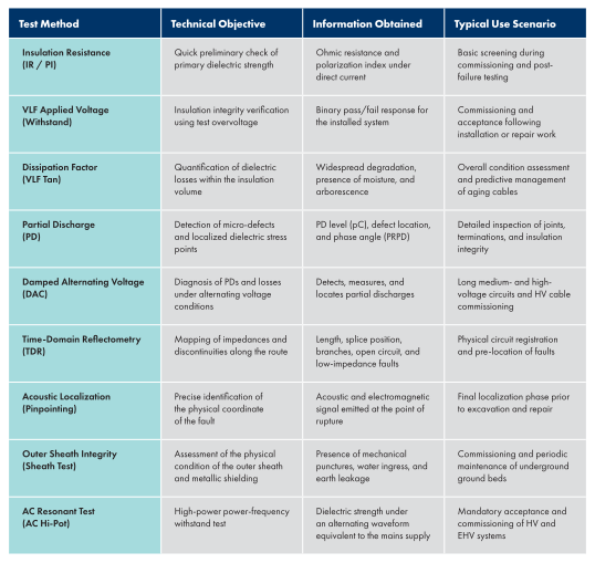
Table 1: Practical Matrix of Test Methods for Insulated Medium and High Voltage Cables
The matrix establishes objective criteria for defining technical inspection routines. Newly executed splices require commissioning inspections focused on PDs and outer sheath tests, capable of identifying assembly deviations before the circuit is delivered for commercial operation. In turn, older lines demand integrated evaluations by VLF tan δ, aiming to monitor the rate of evolution of volumetric degradations resulting from service time and load cycles of the system.
CONCLUSION
Underground networks in industrial environments and distribution utilities operate based on similar electrotechnical principles, yet they require distinct maintenance philosophies due to their architecture and the consequences of potential failures. In the manufacturing sector, the priority is ensuring supply continuity for continuous production lines, where the cost of downtime outweighs the investment in advanced predictive diagnostics. In the distribution sector, management focuses on balancing service availability for the community, regulatory continuity targets, and the efficient allocation of maintenance and network expansion budgets.
The management of medium- and high-voltage insulated cables should not be limited to isolated checks of operation under nominal conditions. A structured maintenance policy aims to determine the degree of insulation degradation, the rate at which it progresses, the mechanisms involved, and the probability of failure during continuous operation. Modern predictive maintenance tools—such as VLF testing, dissipation factor analysis, PD monitoring, time-domain reflectometry, and cable jacket testing—provide the technical data necessary for this assessment.
The modernization of generation, transmission, and distribution sectors, as well as industrial plants, stems from the transition from corrective and reactive maintenance models to CBM and RBM strategies. Transforming field measurements into health and probabilistic risk indicators enables engineering teams to plan interventions before unplanned faults occur, thereby preserving the service life of underground assets that are strategic to national grid reliability.
REFERENCES
- CIGRE TB 924 (2024). Condition Assessment and Diagnostic Methods to Support Asset Management of MV Cable Networks. WG B1.58, 2024.
- ANSI/NETA ATS-2025. Standard for Acceptance Testing Specifications for Electrical Power Equipment and Systems.
- ANSI/NETA MTS-2023. Standard for Maintenance Testing Specifications for Electrical Power Equipment and Systems.
- IEEE 400.2-2024. IEEE Guide for Field Testing of Shielded Power Cable Systems Using Very Low Frequency (VLF) (Less than 1 Hz).
- IEEE 400.3-2022. IEEE Guide for Partial Discharge Field Diagnostic Testing of Shielded Power Cable Systems.
- IEEE 1234-2019. IEEE Guide for Fault-Locating Techniques on Shielded Power Cable Systems.
- CIGRE TB 912 (2023). Condition Evaluation and Lifetime Strategy of HV Cable Systems. CIGRE, 2023.
- IEEE 400.4-2015. IEEE Guide for Field Testing of Shielded Power Cable Systems Rated 5 kV and Above with Damped Alternating Current (DAC) Voltage.
- CIGRE TB 825 (2021). Maintenance of HV Cable Systems. CIGRE, 2021.

Nilson Baroni Jr., PMP, is currently the Operations Director of BAUR USA Corp. He is a Senior Electrical Engineer with more than 34 years of experience leading teams and managing projects in the engineering, operations, and maintenance of low-, medium-, and high-voltage electrical networks in the overhead and underground segments in the largest electric utility in Brazil. Baroni is an experienced international speaker on topics related to electric utilities.

Daniel Bento, PMP, is the CEO of BAUR do Brasil and BAUR USA Corp. He is an Electrical Engineer with more than 30 years of experience in medium-voltage insulated cable networks. He is a former coordinator of CIGRE Study Committee B1 on insulated cables and co-author of CIGRE Technical Brochures 773 and 924 on fault location and cable diagnostics. He was the technical lead for the entire underground distribution network in São Paulo, Brazil.

Marcelo Plantier currently works as an Application Engineer at BAUR do Brasil, providing technical support, training, and solutions for high-voltage testing and diagnostic equipment. He is an Electrical Engineer specializing in power electrical systems, with 8 years of experience in testing and diagnostics of underground insulated power cables, as well as maintenance of electrical power equipment.