
With the fast-tracked planned installations of utility-scale inverter-based resource (IBR) power plants to the bulk power system, utilities, consultants, EPC contractors, and developers are all seeking methods to standardize protection and control (P&C) designs to hasten project execution. Many of these power plant designs incorporate a high-voltage (HV) section or sections, a pooling bus (PLB) section or sections, and collector bus (CLB) sections.
This article explores a typical utility-scale photovoltaic IBR power plant incorporating all these sections and suggests architectures for standardized yard-to-merging unit connectivity. It also addresses the use of partially centralized protection solutions to hasten project execution and further increase standardization. As most of these power plants follow standardized approaches for the power infrastructure, the protection and control can also provide a high degree of standardization.
RENEWABLE POWER PLANT DESIGN
CLBs and PLBs are used in renewable power plants such as wind or photovoltaic (PV) power stations to manage the power flow from the generation source to the transmission grid. In these distributed generation projects, power is produced by many individual sources, such as wind turbines or solar panels. Each of these sources generates a relatively small amount of power at low- or lower medium-voltage levels (480 V–4.160 V).
The collector substation aggregates this power and combines it into a major block of power at a higher medium voltage (13.8 kV–69 kV). These major blocks of power are then combined into output that can be fed into the transmission grid at HV level (115 kV–230 kV plus). Managing and utilizing the power generated by these distributed sources would be difficult without CLBs and PLBs, which serve as critical links between the renewable power sources and the main power grid.
Factors to consider in CLB and PLB designs:
- The design seeks to minimize losses and voltage drops within budgetary constraints.
- Factors considered in interconnecting cable design include cost, real power losses, and voltage drop. A typical design goal is to keep average real power losses below 1%. At full output, real power losses can be as much as 2% to 4%.
- Interconnecting cabling from IBR sources to the collector buses and to step-up transformers between the collector and pooling buses is typically underground.
- Metal-clad switchgear in weatherproof enclosures is often used for CLBs at 15 kV and below.
- At higher medium-voltage levels, PLBs are typically outdoor air-insulated designs using vacuum breakers.
Figure 1 compares and contrasts a traditional utility-scale powerplant with a single power source with an IBR renewable plant with hundreds of smaller energy sources.
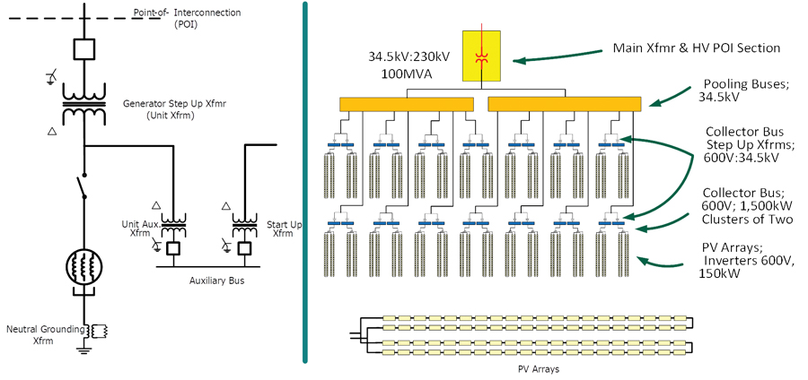
The plant’s various buses and voltage levels are listed below:
- Two identical PLBs are used, each with seven sources: air-insulated switchgear (AIS) and outdoor CBs.
- Seven identical sources feed each PLB input.
- The 28 CLBs are identical LV switchboards in weather-proof enclosures.
- CLB connections are 10 150-kW, 600-V inverters, a feeder to supply auxiliary power, and one output to the CLB step-up Xfmr.
- Two CLBs are grouped per PLB input.
- Two PLBs are input into the main Xfmr.
We will make use of standard infrastructure topology to develop a standard approach to the protection schemes using digital substation techniques.
PROTECTION PHILOSOPHY AND DESIGN
An economic protection method is to employ partially centralized systems with the collector and pooling buses. Partially centralized systems combine an element suited for a given zone or zones of protection, plus multizonality, which protects different zones with the same protection system.
For our study, we assume two protection systems are used for application in partially centralized distribution protection schemes:
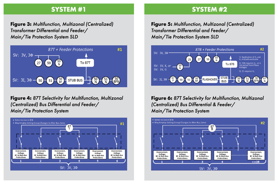
- System #1. A transformer protection system that can cover <=6 nodes, using a definable and selectable transformer differential zone, with all nodes employing overcurrent, voltage, and frequency elements.
- System #2. A combination bus/feeder, main, tie CB protection system that can cover <=28 nodes of primary bus differential protection with phase and neutral/ground overcurrent, overvoltage, neutral overvoltage and breaker failure protections for each node. The differential protection can be divided into <=3 zones.
Single-line drawings (SLD) of the two systems are shown in Figures 3, 4, 5, and 6.
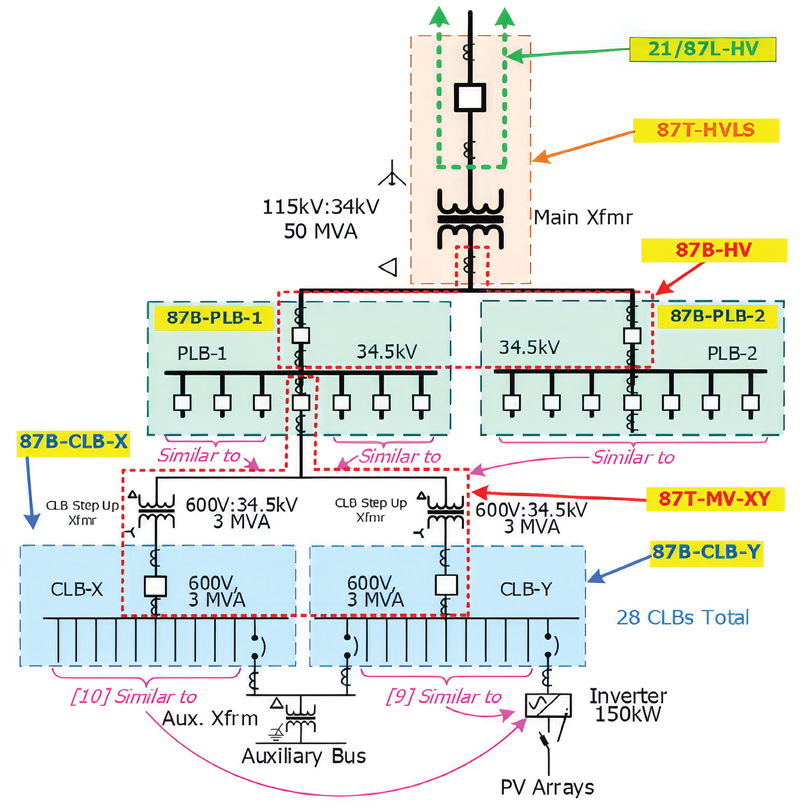
Figure 2 describes the infrastructure and protection application:
- For CLB main CBs and the cabling to the main Xfmr low-side CTs, one System #2 will cover two CLB main CBs and cabling to the main step-up Xfmr low-side winding.
- For the main Xfmr, two System #1s will provide redundant coverage.
- For the HV utility POI, two-line protection systems will provide coverage.
- Six modular units (MUs) will be used to provide redundant HV POI line protection, redundant main Xfmr protection, and non-redundant PLB to main Xfmr low-side bus protection.
This will be shown in detail from the CLB to the utility point of interconnection (POI).
MU Connectivity and Protection: CLB
Figure 7 describes the infrastructure and protection application for CLBs; System #2 will cover two CLBs.
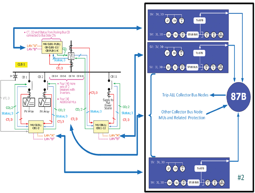
- Seven groups of two CLBs per PLB input; two CLBs are connected to each PLB.
- Each CLB has 10 inverters, one auxiliary source, and one main as nodes (12 nodes total).
- Overcurrent, voltage, and breaker failure protection are provided for all nodes.
- Each CLB is a 12-node 87B zone, 87CLB-X, and 87CLB-Y.
- Total nodes used by CP#2 = 12+12 = 24 (<=28).
- Non-redundant protection for the set of two CLBs will require one Protection System #2.
- Non-redundant protection for the set of two collector buses application will require 14 MUs.
- For nodes on the CLB, System #2 provides bus differential protection. For a bus differential trip, all CBs connecting the CLB are tripped.
- A breaker failure (BF) of the main CB will be cleared by an upline PLB input CB.
Note: All MU-relay signals are transmitted through a networked connection. Connections shown here show relationships only.
MU Connectivity and Protection: CLB to PLB, CLB 87B
System #1 provides overcurrent, voltage, and BF protections for the two CLB main CBs and the PLB input CB (Figure 8). The respective CB is tripped for any protection trip. In the case of BF, all CBs connecting the CLB are tripped.
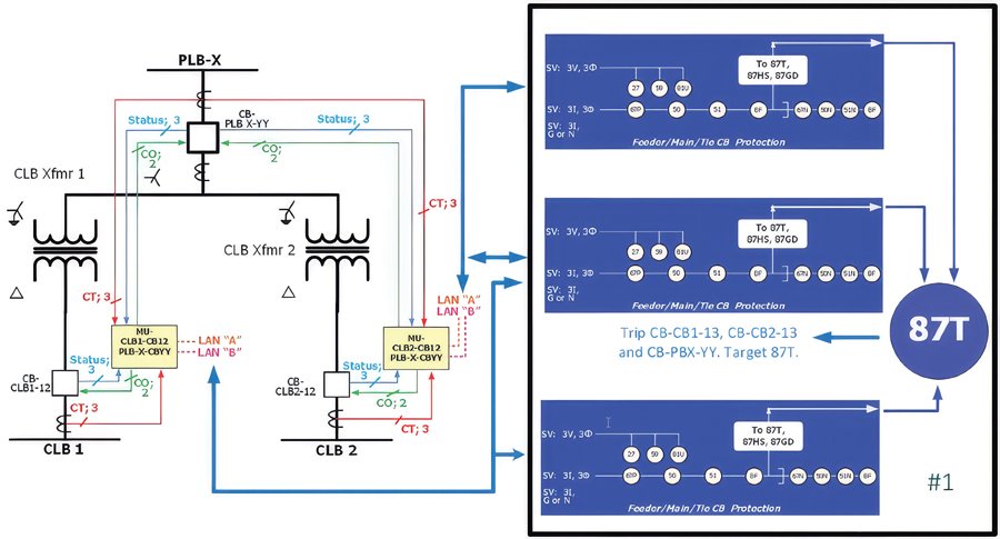
System #1 provides transformer and cable differential protection for the zone between the two CLB CBs and the PLB input CB. For a transformer or cable differential trip, two CLB CBs and a PLB input CB tripped. A BF of a PLB input CB will clear the respective PLB.
MU Connectivity and Protection: PLB
System #2 provides overcurrent, voltage, and BF protections for the PLB input and main CBs (Figure 9). The respective CB is tripped for any protection trip. In the case of BF, all CBs connecting the PLB are tripped.
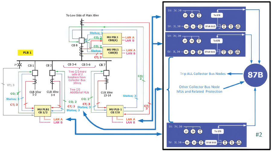
System #2 provides bus differential protection for nodes on the CLB. For a bus differential trip, all CBs connecting the CLB and PLB tripped. A BF of a PLB main CB will trip CB M.
Description of infrastructure and protection application:
- System #2 will cover two CLBs.
- Yard-to-MU connectivity for PLB 1; PLB 2 is similar.
- Non-redundant protection for the set of two CLBs will require one Protection System #2.
- Total nodes used by CP#2 = 8+8 = 16 (<=28).
- Non-redundant protection for the set of two collector bus applications will require eight MUs.
- Redundant MUs on the PLB Main CB bus side are part of the main Xfmr 87T (HV, NERC).
Protective Relay – MU Relationships: Main Xfmr 87T
System #2 provides overcurrent, voltage, and BF protections for the two PLB Main CBs (Figure 10). The respective CB is tripped for any protection trip. In the case of BF, all CBs connecting the PLB are tripped.

System #2 provides bus differential protection for the two PLB Main CBs, cables between the PLB and Main Xfmr, the Main Xfmr, and CB-M. For a bus differential trip, all CBs connecting the PLB and the utility POI (main CB) are tripped. Two System #2s are used for the required redundancy. A BF of a PLB output CB will clear all respective PLB CBs. A BF of CB-M will transfer the trip to the upline transmission system CBs.
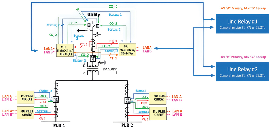
MU Connectivity and Protection: Utility POI
The utility POI dual-line protection systems are employed for the CB-M (Figure 11). Exact element fleet and principle used are dependent on the bulk system owner. CB-M is tripped for any line protection that trips in either redundant protection system. A BF of CB-M will transfer the trip to the up-line transmission system CBs.
CONCLUSION
- In some utility-scale IBR renewable plants, a high quantity of granulized and repeated power infrastructure may be used. These designs lend themselves to the use of centralization for a high degree of standardization in the P&C design.
- Savings on the number of protective devices, panels, and space inside the control house can be obtained. In Greenfield applications, MUs can often be housed in breaker cabinets and LV switchgear compartments, with attendant enclosure and civil savings.
- As one of its attributes, centralization allows economical application of primary and backup functions, and a significant amount of standardization can occur from the standardized design and fabrication of MU enclosures (if applied). Wiring runs from MUs to the yard elements are short and standardized.
- It is possible to protect high-node-count buses using process bus-enabled protection.
- It is possible to economically deploy cable differential protection using sampled values from cable terminals and defining the cable as a bus zone.
- If the MU information for all accessed points is brought into the control house, operators have full view of every element of the plant, from the high-voltage POI to the individual inverter AC inputs, without having to travel to various areas of the plant.

Wayne Hartmann is an Advanced Applications Advisor for GE VERNOVA, Grid Automation. He explores the application of new technologies in protection and control with electric utilities, industrials, and consultants. He provides market research and ideation for new product development and supports the sales and application teams. Hartmann was in Standards Development at Duke Energy and in Application, Sales and Marketing Management capacities at Beckwith Electric, PowerSecure, GE, Siemens Power T&D, and Alstom T&D. He is a Life Senior Member of IEEE and has served as a main PSRC Committee member for over 30 years, contributing to standards, guides, reports, and tutorials.