
Transformer testing should not end when a value is marked acceptable. Each measurement is a diagnostic clue. When insulation resistance, winding resistance, turns ratio, excitation current, and leakage reactance are interpreted together, they create a clearer picture of transformer health and help engineers energize equipment with confidence.
Transformer testing is often viewed as a sequence of individual tasks. In many field reports, each result is recorded, compared with an acceptance criterion, and then marked as acceptable or not acceptable. This approach is necessary for documentation, but it does not always capture the full diagnostic value of transformer testing.
From my experience as an electrical testing engineer, I believe this is only the first layer of transformer testing. In the field, a transformer does not speak directly. It communicates through measurements. A high insulation resistance value, a small winding resistance deviation, a stable transformer turns ratio (TTR) result, or an unusual excitation current pattern can each reveal something about the condition of the transformer. These values are not just numbers in a report; they are diagnostic clues.
This is why transformer testing should go beyond pass or fail. The purpose is not only to prove that a transformer can be energized. The real purpose is to understand the transformer well enough to energize it with confidence.
A transformer is a complete electrical and mechanical system. It includes insulation, windings, magnetic cores, tap changer contacts, bushings, oil, internal supports, and external connections. Because of this, no single test can tell the full story. Each test provides one diagnostic window, and the engineer’s role is to connect these windows together to form a complete picture.
MOVING BEYOND THE CHECKLIST
Acceptance and commissioning tests are essential because they confirm that a transformer is ready for service. They also provide baseline data that can be used later during maintenance, troubleshooting, and life-extension studies. However, the testing process should not stop at checking whether a number is inside or outside a limit.
For example, an insulation resistance test may show a high resistance value, but this does not confirm that the winding connections are correct. A TTR may confirm the ratio, but it does not prove that the winding resistance is balanced across all phases. A winding resistance test may detect a high-resistance joint or tap changer contact issue, but it does not directly evaluate the magnetic core. This is why transformer testing must be interpreted as a group of related measurements.
In practice, the question should not only be: Did the transformer pass the test? The better question is: What does this result tell us about the transformer, and how does it compare with the other test results?
WHAT FIELD TESTING TAUGHT ME
One important lesson I learned in transformer testing is that a normal result should still be understood, not just accepted. During winding resistance testing, the value may appear acceptable, but how the reading stabilizes can also tell the engineer something about the winding, the test connection, and the transformer’s magnetic behavior.
In turns ratio testing, an abnormal result does not always indicate the transformer has a defect. Sometimes it points to an incorrect test connection, wrong vector group selection, or a misunderstanding between phase ratio and line-to-line ratio. This is where field judgment becomes important. Standards and acceptance criteria guide the engineer, but experience helps the engineer ask better questions: Is the result logical? Does it match the tap position? Does it match the other phases? Does it agree with the previous test? Does another test support the same conclusion?
For me, this is the real value of transformer testing. It is not only about operating the test equipment. It is about reading the transformer condition through several connected measurements.
INSULATION RESISTANCE: THE FIRST VIEW OF INSULATION HEALTH
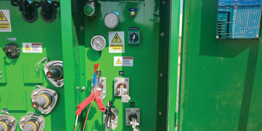
The insulation resistance test (Figure 1) is usually one of the first electrical tests performed on a transformer. It gives an initial indication of the condition of the insulation system between windings and between windings and ground. The test is simple in concept: A DC voltage is applied, and the resistance of the insulation is measured. However, interpretation requires care. The measured value is affected by temperature, humidity, surface contamination, moisture, test voltage, and the condition of the insulation. A low reading may indicate moisture, dirt, insulation deterioration, or leakage paths. It may also be influenced by poor test preparation, dirty terminals, or wet environmental conditions. This is why insulation resistance should be seen as a screening test, not a complete diagnosis by itself. A good insulation resistance value is encouraging, but it does not confirm that the winding geometry, turns ratio, tap changer, or core condition are correct.
WINDING RESISTANCE: SMALL VALUES WITH BIG DIAGNOSTIC MEANING
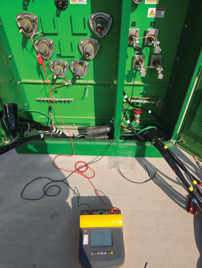
Winding resistance testing (Figure 2) measures the DC resistance of transformer windings. The measured values are usually small, but they carry important diagnostic information. This test can help detect loose connections, high-resistance joints, poor bolted connections, defective tap changer contacts, open circuits, and phase imbalance.

One of the most important parts of this test is comparing phases and tap positions. A single resistance value has limited meaning unless it is compared with the corresponding phases, previous results, factory results, or expected design values.
If one phase shows a noticeably higher resistance than the others, the issue might be related to a loose connection or tap changer contact. If one phase shows a much lower resistance, it could indicate a possible shorted turn or incorrect connection. If the values are unstable during the test, this might suggest poor contact, incomplete core saturation, or an issue in the test connection.
Winding resistance testing also reminds us that field technique matters. Current should be applied carefully, readings should be allowed to stabilize, and the winding should be safely discharged after testing because of the stored magnetic energy in the transformer core.
TURNS RATIO TEST: CONFIRMING THE ELECTRICAL RELATIONSHIP
The turns ratio test (Figure 3) verifies that the relationship between the primary and secondary windings matches the transformer nameplate and tap position. This test is critical because an incorrect ratio can lead to incorrect output voltage, circulating currents in parallel operation, protection issues, and system performance problems.
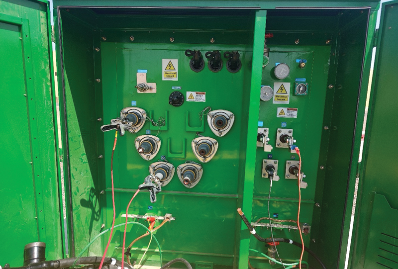
However, turns ratio testing is not just about comparing a single number with the nameplate ratio. The tester must understand the transformer vector group, winding connection, tap position, and whether the calculation should be based on phase ratio or line-to-line ratio.
A common field issue is obtaining an abnormal ratio because the test connections are wrong or because the selected vector group in the test equipment does not match the transformer. In this case, the transformer itself may not be defective; the problem may be in the test setup. This is why a TTR test should always be interpreted with connection verification.
A correct TTR result supports the conclusion that the number of turns and the voltage transformation relationship are correct. But it does not prove that the contacts are healthy, that the insulation is dry, or that the core is free of problems.
EXCITATION CURRENT: LOOKING AT THE MAGNETIC CORE
The excitation current test, also known as the open-circuit test, provides important information about the transformer core and magnetic circuit. During this test, voltage is applied to one winding while the other winding is open, and the current required to magnetize the core is measured.
The excitation current includes two main components: the magnetizing current and the core-loss current. Abnormal excitation current may indicate core problems, shorted turns, tap changer issues, incorrect connections, residual magnetism, or winding defects.
One important part of excitation current interpretation is comparing the pattern between phases. In many transformers, the middle phase might show a different current from the outer phases because of the magnetic path and core construction. Therefore, the result should not be judged only by looking for identical values on all three phases. The expected pattern depends on the transformer design, connection, and previous test records.
Excitation current is powerful because it can reveal magnetic or turn-related problems that might not appear clearly in insulation resistance or winding resistance tests.
LEAKAGE REACTANCE: DETECTING MECHANICAL MOVEMENT
Leakage reactance, or short-circuit impedance testing (Figure 4), is especially valuable for detecting mechanical changes inside the transformer. When a transformer experiences a short-circuit event, transportation shock, or severe mechanical stress, the winding geometry can change. Even a small movement of the windings can affect the leakage flux path and therefore change the measured reactance.
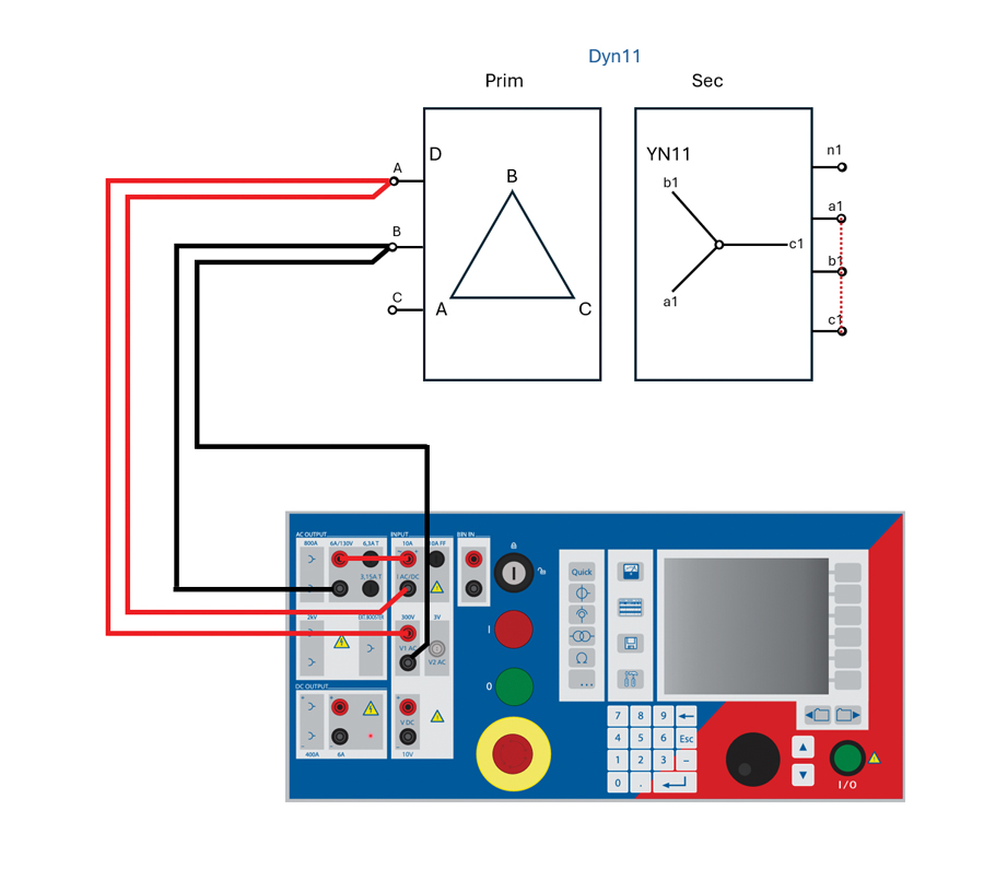
This test is important because some mechanical problems might not be visible externally or strongly affect insulation resistance or TTR results. A transformer could appear electrically acceptable in several tests but still have internal winding movement that increases future failure risk.
Leakage reactance results are most useful when compared with factory test results or previous field results. A significant change from the baseline can indicate winding deformation, displacement, or mechanical damage.
WHY THE TESTS MUST BE READ TOGETHER
The best diagnostic value comes from combining test results. If winding resistance is abnormal on one phase and the turns ratio is also abnormal on the same phase, the problem might be related to the winding or tap changer. If excitation current is abnormal but turns ratio is normal, the issue could be more related to the magnetic circuit, residual magnetism, or core condition. If insulation resistance is low while winding resistance and TTR are normal, the main concern could be insulation moisture, contamination, or surface leakage rather than a winding connection issue.
A transformer test program should therefore connect each test result to a possible transformer subsystem.

This combined approach helps the engineer avoid two common mistakes: accepting a transformer too quickly because one test looks good or rejecting a transformer too quickly because one result looks abnormal without enough supporting evidence.
THE IMPORTANCE OF BASELINE DATA
One of the most valuable outcomes of acceptance testing is the creation of baseline data. The first field test results become a reference for future maintenance and troubleshooting. Without baseline data, it is much harder to determine whether a future result is normal for that transformer or represents a real change.
For this reason, test reports should include more than final values. They should document test conditions, temperature, humidity, tap position, test voltage, equipment used, connection method, and any unusual observations during testing. Good documentation makes future comparison more reliable.
CONCLUSION
As electrical testing engineers, our responsibility is not only to complete the test sheet. Our responsibility is to understand the condition of the equipment we are testing. Transformer testing provides several diagnostic tools, but the real value lies in connecting the results.
Insulation resistance gives a first view of the insulation condition. Winding resistance reveals the health of winding paths and contacts. Turns ratio confirms the voltage transformation relationship and tap position. Excitation current gives insight into the magnetic core. Leakage reactance helps detect mechanical movement or winding deformation.
When these tests are reviewed together, they allow the engineer to move beyond a simple pass-or-fail decision and toward a deeper understanding of transformer health.
For me, this is what makes transformer testing valuable. It is not just a procedure before energization; it is a diagnostic conversation between the engineer and the transformer. The measurements are the transformer’s language, and the engineer’s job is to understand what they mean.
REFERENCES
- ANSI/NETA ATS, Standard for Acceptance Testing Specifications for Electrical Power Equipment and Systems.
- ANSI/NETA MTS, Standard for Maintenance Testing Specifications for Electrical Power Equipment and Systems.
- IEEE. IEEE Std. C57.152, IEEE Guide for Diagnostic Field Testing of Fluid-Filled Power Transformers, Regulators, and Reactors.
- IEEE. IEEE Std. 43, Recommended Practice for Testing Insulation Resistance of Electric Machinery.

Khaled Shadi Morshed is an Electrical Engineer at Commissioning Services International (CSI), where he is involved in testing, commissioning, and power system analysis. He received his BEng from Al-Balqa’ Applied University in Jordan. Morshed is also a NETA Level 3 Certified Electrical Testing Technician, demonstrating his expertise in advanced electrical testing and commissioning procedures.