
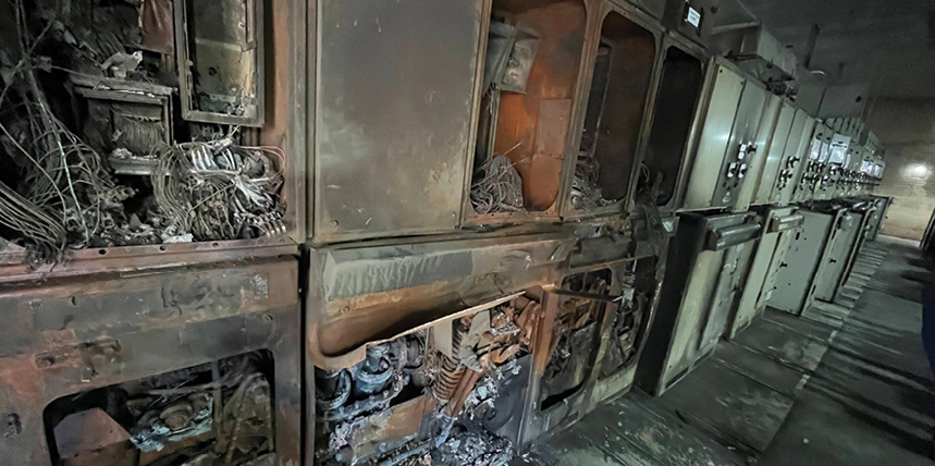
Reliability and safety are words that come up frequently when discussing modern power networks, and for good reason. Electrical systems today are carrying higher loads, operating with tighter margins, and supporting facilities such as data centers and industrial plants, where downtime is not an option. As a result, operators are placing greater emphasis on technologies that provide early warning of developing issues rather than reacting after a failure occurs.
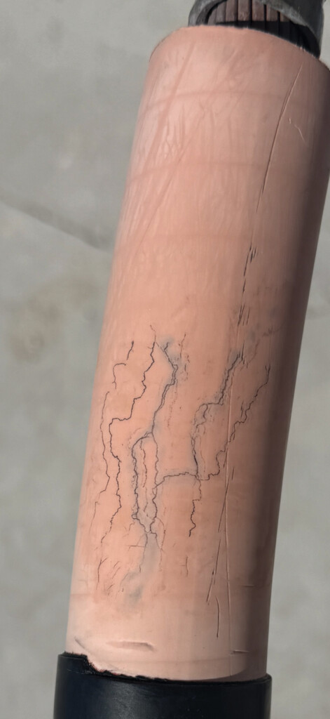
One technology that has gained significant attention in this context is on‑line partial discharge (PD) monitoring. It offers a practical way to continuously monitor the health of medium‑ and high‑voltage power networks without taking assets out of service. While it is difficult to put an exact dollar figure on an outage that never happens, the operational value of avoiding unexpected failures is widely understood. More importantly, knowing the condition of energized equipment in real time helps operators make safer, more informed decisions, protecting people, equipment, and the continuity of operations.
WHAT PARTIAL DISCHARGE IS AND WHY IT MATTERS
Partial discharge is formally defined as an electrical discharge that does not completely bridge the insulation between two conductive parts. In practical terms, PD activity occurs at insulation defects—voids, cracks, contamination, or interfaces—where localized electrical stress exceeds the strength of the material. While individual discharge events may be small, their presence is a well-established early indicator that insulation is degrading.
Left unchecked, sustained PD activity typically accelerates insulation damage and can eventually result in a full dielectric breakdown or fault. This is why PD has long been of interest to those responsible for testing, commissioning, and maintaining electrical assets.
PD can be detected using a wide range of techniques, typically divided between off-line testing and on-line testing. Each method has its place, depending on the asset, operating environment, and maintenance objectives. The focus here is on on-line PD monitoring, which allows condition assessment while equipment remains energized and in service.
A PRACTICAL WAY TO THINK ABOUT PD
A simple analogy helps illustrate the concept. Consider a small leak in a high-pressure pipe. The system continues to operate, sometimes for quite a while, but the integrity of the pipe has already been compromised. Over time, that leak worsens as stress concentrates around the defect, until the pipe eventually fails—often suddenly and with significant consequences.
Electrical insulation behaves much the same way. Once a void or defect develops, partial discharge activity begins. Environmental and operating stressors such as load changes, temperature fluctuations, and transient overvoltage work against the insulation and accelerate damage.
On-line PD monitoring is intended to detect this leak early, allowing operators to plan repairs, divert load, or schedule outages on their own terms rather than reacting to an unexpected failure.
LOOKING BEYOND A SINGLE ASSET
If we zoom out from a single cable and instead consider an entire interconnected electrical system, the implications of insulation degradation become much easier to appreciate. Any one defect may seem insignificant on its own, but across a large network, the cumulative risk grows quickly. The consequences are no longer limited to a single failure; they can include extended downtime, widespread damage, and, in the worst cases, serious safety hazards or loss of property.
It is true that electrical grids and facility power systems have operated for decades without the continuous diagnostic tools available today. However, those systems were also designed for very different operating conditions. Load profiles were smaller, equipment was often overbuilt, and reliability expectations were less unforgiving than they are now. Today’s electrical infrastructure operates closer to its design limits and is subjected to higher and more dynamic stress than ever before.
The additional stress and dynamic load profiles matter. Load cycling, temperature variation, and transient operating conditions all contribute to increased electrical stress on insulation systems. Once a defect exists, these factors do not remain neutral; they actively worsen it.
Let’s go back to the pipe analogy. A small leak under steady conditions may persist for years. Increase the temperature, raise the pressure, and introduce cyclic loading, and that same defect accelerates toward failure. Electrical insulation behaves in much the same manner. A void or imperfection exposed to increased electrical and thermal stress will produce more partial discharge activity and degrade more rapidly over time.
Seen in this context, partial discharge is not abstract, mysterious, or unreliable. It is a measurable, physics‑based response to stress within insulation. What has changed over the years is not the phenomenon itself, but our ability to observe it reliably in real operating environments.
When these factors are taken together, the role of on‑line partial discharge monitoring in supporting safety and reliability becomes clear. Early adopters, especially those responsible for large critical facilities, are incorporating this approach into their maintenance strategies, not as a replacement for established practices, but as a practical supplement to them.
ON-LINE PD MONITORING FILLS A PREVIOUSLY UNKNOWN GAP
For operators managing large electrical networks such as data centers, industrial facilities, or utility systems, on‑line PD monitoring provides tangible operational advantages. Continuous insight into asset condition allows maintenance decisions to be based on actual system behavior rather than elapsed time alone. In some cases, maintenance intervals can be confidently extended or deferred when condition data confirms acceptable performance. In others, emerging PD activity highlights exactly where attention is needed, enabling targeted shutdowns instead of broad, disruptive outages.
When integrated into existing maintenance or building management systems, PD alarms and condition indicators can flow naturally into established workflows, often autonomously initiating inspections, guiding prioritization, and helping teams respond early rather than react late. The result is a condition‑based maintenance approach that focuses time and resources where they provide the most value, while minimizing unnecessary downtime.
Advances in technology have also made on‑line PD monitoring far more practical to deploy. Modern systems can be implemented in both new and existing installations. New facilities may incorporate monitoring during construction for optimal coverage, while existing sites can often be retrofitted without major redesign or disruption. Broad compatibility with common switchgear and cable systems has reduced the barriers that once limited adoption, making large‑scale deployment a realistic option for many operators. Modern systems allow for installation without taking shutdowns and allow for maintenance access without requiring labor intensive removal of the system.
THE NOISE REJECTION ARGUMENT
One of the most common questions surrounding on‑line PD monitoring is straightforward: How do you know it’s actually PD and not just noise?
This is a valid concern. In energized environments, particularly in underground medium‑voltage cable systems, PD signals can be very small and easily masked by ambient electrical noise from normal system operation, power electronics, and external interference. Historically, addressing this problem required a two‑step approach: collecting field data and then relying on off-line expert analysis to separate PD activity from noise. While effective for limited deployments, this method becomes impractical in large facilities where hundreds or thousands of assets must be monitored continuously.
To be viable at scale, modern PD monitoring systems must operate with a high degree of autonomy. That means filtering noise, classifying pulse characteristics, and identifying meaningful events without constant manual intervention. Accuracy is critical, as false positives quickly erode confidence and place an unnecessary burden on maintenance teams.
Reliable autonomous detection depends on both high-quality data and advanced analysis techniques. Modern systems typically employ high sampling rates and sufficient bit resolution to capture the fine detail needed for effective pulse discrimination. This level of fidelity enables advanced signal processing methods to distinguish legitimate PD pulses from background interference.
Over time, trending becomes just as important as individual events. By establishing baselines and tracking changes in activity, monitoring systems can highlight gradual degradation that might otherwise go unnoticed. This long-term perspective allows operators to intervene early, well before conditions become critical.
THE ON-LINE MONITORING STACK
While on-line partial discharge monitoring systems may look different from one manufacturer to the next, the underlying building blocks are largely the same. At a high level, every system comprises three functional layers: sensors, signal processing, and data interpretation (Figure 1). Understanding this basic stack goes a long way toward removing the mystery often associated with PD monitoring.

At the lowest level are sensors, which are the components that interact directly with the electrical asset. Sensor form and detection styles vary (Figure 2), but they all work to detect the same physical phenomenon: rapid energy release caused by partial discharge.
Acoustic sensors, which are seen in many on-line monitors and handheld detectors, listen for PD activity by detecting ultrasonic energy produced when a discharge happens. These sensors are typically line-of-sight devices and are most effective when placed close to the source, such as on switchgear or accessible cable terminations.
Transient earth voltage (TEV) sensors detect very-short-duration transients that occur on grounded metal surfaces when PD occurs inside enclosed equipment. These signals are extremely small, comparable in magnitude to static electricity, so these sensors utilize capacitive coupling to make them measurable.
High-frequency current transformers (HFCT) take a different approach. Installed around a ground conductor or cable shield, they detect high-frequency current pulses associated with partial discharge events. Rather than listening or sensing voltage, HFCTs observe how PD activity manifests as current in the grounding system. Examples of these types of sensors can be seen in Figure 2.

While the form and placement of these sensors vary, the same purpose is served: converting a physical event into an electrical signal that can be measured.
Translating signals into data is accomplished by transmitting captured analog or digital data to a processing device such as an industrial computer or embedded processor. This step is where much of the historical skepticism around PD monitoring has originated. Raw PD signals, taken alone, often look messy and are easily confused with background noise from normal system operation.
Modern systems address this by digitizing signals at high speed and applying structured processing. The goal is not to capture every fluctuation, but to identify patterns that match known PD behavior while rejecting unrelated interference. In other words, the system is not guessing—it is filtering, comparing, and classifying events based on consistent rules. Depending on system architecture, this processing may take place locally at the device or be supported by centralized infrastructure.
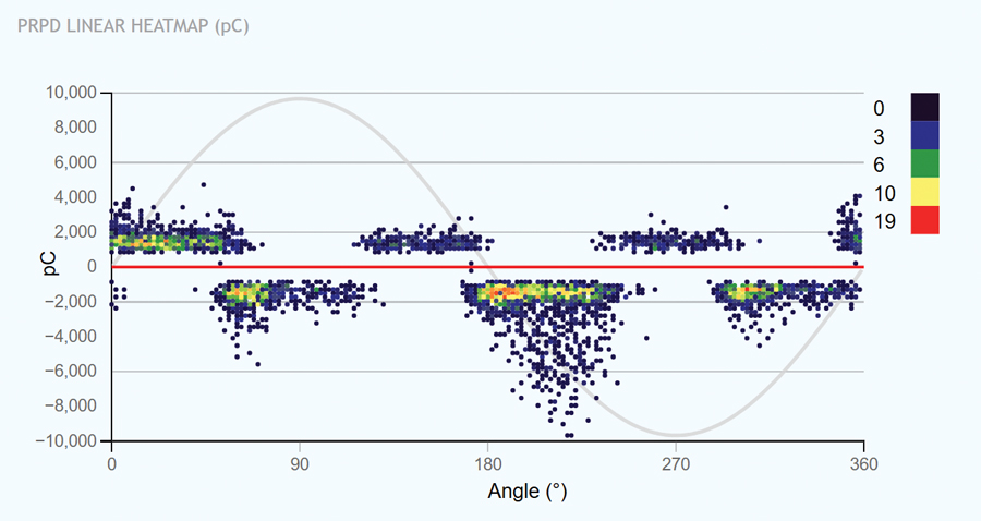
The final layer is interpretation. Rather than expecting operators to interpret raw waveforms, modern monitoring platforms focus on trends, alerts, and condition indicators that fit naturally into existing maintenance workflows. A practical example of this translation is the use of real‑time phase‑resolved partial discharge (PRPD) heatmaps (Figure 3), where complex signal data is converted into recognizable visual patterns that support consistent interpretation. When PD activity changes over time, the system highlights that shift so it can be investigated before it develops into a failure.
Seen this way, on-line PD monitoring is not fundamentally different from other condition monitoring technologies already in use. Sensors observe a real physical phenomenon, processors clean and organize the data, and the results are presented in a way that supports informed decision-making. Once the technology stack is understood as a whole, it becomes clear that on‑line PD monitoring is not guesswork or black magic, but a structured process of precise data collection and interpretation.
Permanent monitoring is not always practical or necessary for every asset, which is where portable and handheld PD survey instruments continue to play an important role. These tools are particularly useful for screening unmonitored equipment and for locating the physical source of PD activity identified through continuous monitoring.
Handheld instruments (Figure 4) range from simple go/no‑go devices to more advanced tools incorporating noise filtering and PRPD pattern analysis. When used as part of a broader condition‑based maintenance program, they provide a flexible and cost‑effective way to extend diagnostic capabilities into the field.

MODERN DATA ANALYSIS
Interpreting PD data still requires experience and a solid understanding of discharge mechanisms and severity. Expert analysis remains essential, particularly when determining root cause and appropriate corrective action. However, modern monitoring platforms increasingly help by summarizing large data sets into clear indicators of asset health and risk.
When applied correctly, this information allows maintenance teams to prioritize inspections, plan targeted shutdowns, and address issues before they escalate into failures. Identifying insulation defects early not only improves reliability but also makes repairs safer, more efficient, and less disruptive.
On-line PD monitoring enhances traditional testing and maintenance by providing continuous visibility into insulation health, enabling earlier, better‑informed decisions. When integrated thoughtfully, it supports a holistic approach to electrical system reliability, helping operators meet today’s demands while preparing for the challenges ahead.
CONCLUSION
Partial discharge isn’t witchcraft—it’s a predictable, measurable response to insulation stress. Electrical systems today operate under higher loads, tighter margins, and greater thermal and operational stress than in the past, which accelerates insulation defects once they exist.
What’s changed isn’t the physics of partial discharge, but our ability to observe it reliably while equipment is energized. On-line PD monitoring gives operators continuous, practical insight into asset condition, allowing maintenance decisions to be based on real behavior rather than tradition or fixed schedules. The result is safer operation, fewer unplanned outages, and more focused, condition based maintenance across large electrical systems.

Bobby Ellison is a Senior Project Engineer at IPEC with more than a decade of experience spanning critical power systems, field operations, project engineering, and customer-focused technical strategy. He began his career with Cummins Inc., building a strong technical foundation through hands-on work in emergency and critical power environments. Known for his steady leadership approach, technical credibility, and ability to align teams and customers, Ellison brings a pragmatic, execution-focused mindset that consistently turns technical challenges into practical business value.