
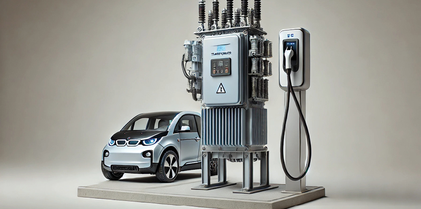
Electric vehicles (EVs) are a large part of the traffic infrastructure due to the industrial revolution in electrical technology and the paradigm shift in the motor vehicle industry. To support this rapid growth in EVs, the charging infrastructure would need to be designed and implemented at scale. This phenomenon has caused an explosive growth in the design, development, and construction of electric vehicle supply equipment (EVSE).
EVSE refers to the charging infrastructure that safely delivers electrical energy from the power grid to an EV. It includes all the external hardware—such as transformers, overcurrent protective devices (e.g., circuit breakers or fuses), cables, connectors, enclosures (e.g., panel or junction boxes), and control systems—that ensure the proper and safe transfer of electricity for recharging the EV’s battery. EVSE could contain all or some of the components, depending on the different voltages and types of charging mechanisms. EVSE is designed to manage and regulate the electrical connection, provide safety features like isolation and fault detection, and often includes communication protocols to coordinate with the vehicle’s onboard charger.
Essentially, while the EV contains its own charging components, the EVSE is the external system that provides the interface between the grid and the vehicle. According to the U.S. Department of Energy, EVSE is not simply a plug or charger; it is an integrated system designed to meet strict safety and performance standards for both the vehicle and the electrical grid.
TYPICAL EVSE AND EV CHARGER SETUPS
EVSE can be found in many different configurations and setups. This depends on the customer’s preference on the design, supply power abilities, and location for the EVSE setup. NFPA 70, National Electrical Code, Article 625 Electric Vehicle Power Transfer System consists of all EV charging conductors and equipment external to the vehicle, including Level 1, Level 2, and DC Fast Chargers. This is one of the most important references for designing the EVSE. Several other standards—such as UL 2594, EV Supply Equipment; UL 2202, DC Charging Equipment for EVs; IEEE Std. 2030, Smart Grid Interoperability; and IEEE P1547.9, IEEE Guide for Using Std. 1547 for Interconnection of Energy Disributed Energy Resources with Electric Power Systems, etc.—can be referred to while designing EVSE. Local city and state jurisdictions should be consulted for meeting and adhering to the code for a robust and effective design.
For the scope of this paper, only Level 2 EV chargers are considered. The EVSE and EV charger setup and their potential electrical risk assessment methods, data collection, engineering software modeling, and analysis are included. Data was collected by visiting nine different buildings in a large federal facility with this Level-2 charging infrastructure. Each building has at least two charging ports; one building has 16 charging ports. The nameplate information for three-pole 480-V circuit breakers and/or low-voltage disconnect, transformer, 208-V panel, two-pole feeder circuit breakers, and conductor lengths was gathered. Any engineering software capable of modeling short circuit and arc flash hazard analysis can be utilized to create the EVSE power system model and perform risk assessment.
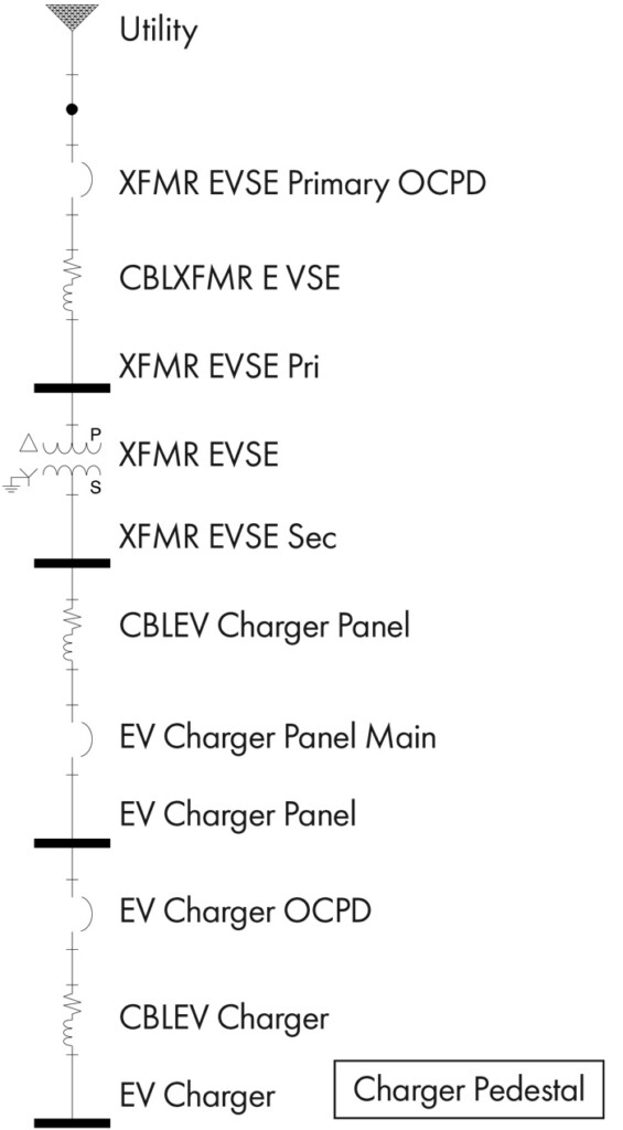
The common design constraint in all of these buildings was typically a 480-V power supply from existing panels. This overcurrent protective device (OCPD) was a thermally magnetic molded-case circuit breaker with no adjustable settings. This OCPD was sized appropriately to protect a dry-type transformer that had a NEMA 3R enclosure. All the transformers were 480-V to 208-V step-down transformers. The downstream of these transformers was connected to a 208-V three-phase panel with a main circuit breaker (MCB). Some of the MCBs had electronic trip units with long time, short time, and instantaneous (LSI) trip settings, and others were thermal magnetic MCBs with fixed instantaneous trip units. All feeder circuit breakers that provided 240-V power to the EV chargers were standard two-pole thermal magnetic MCBs with a fixed trip unit. All the chargers were no farther than approximately 50 feet from the panel. This design configuration is shown in Figure 1.
EVSE AND EV CHARGER ELECTRICAL HAZARDS
EVSE and EV chargers should be installed properly according to applicable standards and OEM instructions. Typically, these pose hazards similar to those of other electrical equipment, including arc flash, arc blast, and electric shock if exposed to energized components. The batteries in the EV, while charging, may pose additional hazards such as electrical and/or chemical fires and/or chemical exposure. If the charger units are not grounded properly, the charger handle may cause some electrostatic discharge and shock. If the charger cables are not placed correctly after use and sustain any tear in the insulation, this may lead to serious electrocution and arc flash hazards. Most of this infrastructure is located outdoors, so the enclosures should meet the applicable NEMA standards. All of these hazards tend to be serious and multiply when conditions are rainy or wet. Failure Modes and Effects Analysis (FMEA) was performed for the electrical hazards (Table 1).
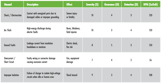
Notes for FMEA Calculations: Severity (S) = 1 (minor) to 10 (catastrophic) • Occurrence (O) = 1 (rare) to 10 (frequent) Detection (D) = 1 (easy to detect) to 10 (hard to detect) • Risk Priority Number (RPN) = S X O X D
The goal of this exercise was to calculate the risk using numerous factors such as severity, occurrence, and detection. These calculations are based on general industry knowledge. It is recommended to perform FMEA calculations based on the electrical risks from the reader’s perspective. These calculations were performed to provide an idea for quantifying the electrical hazards.
ELECTRIC SHOCK HAZARD RISK ASSESSMENT
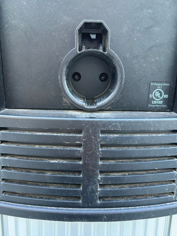
The electric shock hazard assessment was performed separately for the EV charger and EVSE. For EV chargers, there are no exposed electrical conductors while charging handles are plugged into the charging station. Per OEM and industry standards, power is terminated when not plugged in to charge the vehicle. The charging cord plugs are designed according to the SAE J1772 and UL 2231–2 standards. Since the nominal voltage is 240 V and there are no exposed energized parts, there is no electrical shock hazard.
For the EVSE, there are no exposed electrical conductors. All EVSE components, such as transformers, disconnects (if any), 208-V panel, and cables, are enclosed in an appropriately rated NEMA 3R enclosure (Figure 2). All covers are in place, and all the hardware is fastened per OEM guidelines. When covers are removed, there are shock hazards as listed below:
- Nominal Voltage = 208 V/240 V
- Limited Approach Boundary = 42 inches
- Restricted Approach Boundary = 12 inches
This is derived from NFPA 70E–2024 Edition, Table 130.4(E)(a) Electric Shock Protection Approach Boundaries to Exposed Energized Electrical Conductors. These boundaries are applicable to 208-V, 240-V, or 480-V power systems.
Per this unit’s manufacturer, the EV charger has 20-mA charge current interrupting device (CCID) ground-fault detection. A CCID is essentially a smart switch that monitors the flow of current in the charging cable. When the CCID detects a fault, it interrupts the flow of current, thus preventing any further damage. The CCID is typically installed as a part of the charging station’s interior controls, working like the GFCI principle. This EV charger also has an open safety ground detection feature, which continuously monitors the presence of a safety ground connection. The cord had plug-out detection features per SAE J1772, and the power is terminated once the charger is removed from the plug.
ARC FLASH HAZARD RISK ASSESSMENT
Like the electric shock hazard assessment, the arc flash hazard risk assessment was performed separately for the EV charger and EVSE. The software model was created for all nine buildings, and incident energy was calculated in the EVSE distribution panel and EV charger. All calculations were performed according to IEEE 1584–2018 and NFPA 70E–2024 for the working distance of 18 inches. Table 2 consists of incident energy and arc flash boundary calculations for the EVSE distribution panel, and Table 3 consists of similar calculations for the EV charger.
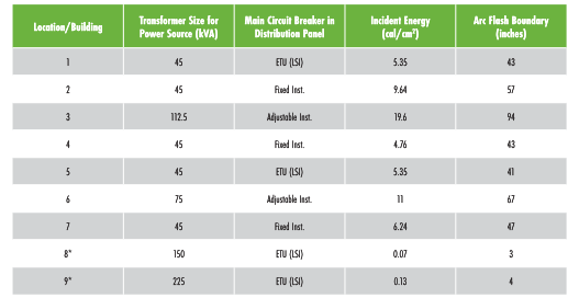
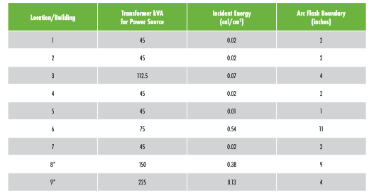
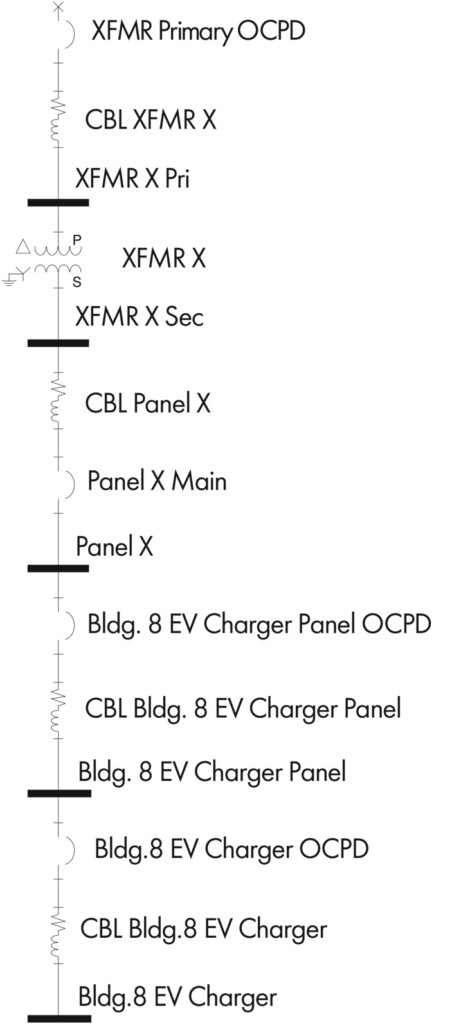
Most buildings have the power system shown previously in Figure 2 with the dedicated transformer for EVSE and then subsequent downstream equipment for EV charger. Building 8 and Building 9 have a different power system for EVSE as shown in Figure 3. These buildings have a separate EVSE distribution panel but share a common transformer, larger in size compared to the other buildings.
The common trend for all the buildings is that the incident energy in the EVSE distribution panel is directly proportional to the transformer size, where the transformer is dedicated to the EVSE. There was a slight difference in incident energy for the EVSE distribution panel, which had an electronic trip unit in its MCB, compared to the fixed trip unit counterparts. The average arc flash boundary is 48 inches except for the panel being fed by a 112.5-kVA transformer. Most of the EV chargers were about 8 to 10 feet away from the parking lot for all buildings.
The incident energy for all EV chargers was significantly lower than EVSE. This is a typical result found in arc flash hazard calculations since this equipment is downstream of the EVSE transformers. The average incident energy is 0.13 cal/cm2, and the arc flash boundary is about 4 inches. Most users are always out of this arc flash boundary while using the chargers, and the charging plug is almost 5.2 inches long, which is outside of the arc flash boundary.
The incident energy and arc flash hazard analysis align with the typical power system hazard analysis. The further downstream we go from the transformers, the lesser the incident energy. Most of the overcurrent protective devices cleared the fault according to their respective fault-clearing times. There were some scenarios where the fault-clearing time was 2 seconds. In other terms, a fault has occurred, the protective device has yet to clear the fault, and it becomes the technician’s responsibility for his/her safety to react and leave the arc flash boundary. Based upon IEEE Std. 1584, Annex B.1.2, personnel working near the fault will react and leave the arc flash boundary within two seconds.
FURTHER WORK
This paper only included Level 2 chargers from certain manufacturers in the analysis. There are several other EV chargers that are different from these in capacity, type, charging mechanism, and design. The plan is to build on this research, gather additional field data, and perform risk-hazard analyses across multiple EV chargers. Another goal is to conduct more research on other possible hazards, such as explosions, electric fires, thermal runaway on batteries, etc. The ultimate goal would be to combine the EVSE, EV chargers, and EVs and calculate/analyze the hazards for the entire system. This field is rapidly evolving with advances in technology, and many variables have been introduced to make it a safer, user-friendly system.
CONCLUSION
EVSE and EV chargers are an essential part of modern technology. They use electrical power on the scale of 208 V/240 V or 480 V with several Amps (40–100) in range, so there are always going to be inherent electrical hazards as with other electrical equipment. This infrastructure should be installed according to manufacturer (AHJ) specifications, and local authority having jurisdiction (AHJ), and well-maintained according to applicable NFPA 70B and/or OEM specifications. Well-maintained EVSE and EV are less likely to have significant failures compared to neglected ones. Like other electrical equipment, they will improve our standard of living and enhance technology if we take care of them and understand the hazards around them.
REFERENCES
- U.S. Department of Energy (DOE). “Alternative Fuels Data Center: Electric Vehicle Charging Stations,” afdc.energy.gov, (July 6, 2026). Accessed at afdc.energy.gov/fuels/electricity-stations.
- SKM Power Tools. SKM Systems Analysis, Inc. – Power System Software and Arc Flash Hazard Analysis and Design Solutions.
- National Fire Protection Association. NFPA 70E, Standard for Electrical Safety in the Workplace,® Table 130.4(E)(a) Electric Shock Protection Approach Boundaries to Exposed Energized Electrical Conductors or Circuit Parts for Alternating-Current Systems, 2024.
- ChargePoint. Home Flex Data Sheet. docs.chargepoint.com/ref-docs-sec/content/pdfs/1-home/flex/flex-ds.pdf. Accessed: Dec. 13, 2025.
- IEEE. IEEE Std. 1584–2018, IEEE Guide for Performing Arc Flash Hazard Calculations, Annex B.1.2.

Bibek Karki is a Director of Engineering at IPS PowerServe, with more than 12 years of industry experience in power system studies, electrical consulting, testing, and maintenance. A senior IEEE member, Karki is a Registered Professional Engineer in 26 states, a Certified Electrical Safety Compliance Professional (CESCP), a NETA Level 4 Certified Senior Technician, a NICET Level III Technician, and holds Sigma Black Belt certification. He holds an MS in electrical engineering from Southern Methodist University.