

Transformer Turns Ratio (TTR) testing is a fundamental diagnostic method used to verify transformer winding integrity, tap-changer position, and compliance with nameplate data by comparing measured voltage ratios with theoretical values. This test enables early detection of winding deformation, incorrect internal connections, manufacturing defects, or tap-changer issues. However, when applied to rectifier transformers, complexity increases significantly due to multiple secondary windings, specialized interconnections, and intentional phase shifts required for multi-pulse rectification.
Hydrogen production rectifier transformers used in industrial rectifier and power electronic applications present unique challenges that differentiate them from standard power transformers. These units often incorporate complex winding arrangements, phase-shifting windings, and multiple vector groups within a single transformer to achieve multi-pulse rectification, such as 24-pulse configurations. As a result, the internal electrical relationships between windings are inherently more complex and cannot be accurately evaluated using conventional three-phase TTR test methods.
In a rectifier transformer, phase displacement, asymmetrical winding geometry, and internal interconnections may produce misleading results when standard TTR techniques are applied. This can increase the risk of false indications or, conversely, mask actual winding or connection issues. For this reason, IEC 61378-1 defines specialized test methodologies specifically tailored to the construction and electrical behavior of rectifier transformers.
This case study focuses on the application of the IEC 61378-1 single-phase cyclic permutation method for TTR testing of a three-winding, 24-pulse hydrogen production rectifier transformer. The objective is to demonstrate how this methodology enables accurate, repeatable, and directly comparable field measurements, even in the presence of complex vector groups and phase-shifting connections. The study further validates the effectiveness of this approach by directly comparing field test results with factory acceptance test (FAT) measurements.
For consistency and direct comparability, this case study is based exclusively on transformer turns ratio (TTR) measurements performed at Tap Position 1. Field tests and factory acceptance test results correspond to the same tap position, ensuring that the comparison reflects test methodology performance rather than tap-dependent variations.
CHARACTERISTICS OF A 24-PULSE HYDROGEN PRODUCTION RECTIFIER TRANSFORMER
The rectifier transformer for hydrogen production is not a standard transformer. It is a specialized power-supply device designed specifically for the high-energy, continuous process of water electrolysis. It integrates voltage transformation, electrical isolation, and harmonic management. A 24-pulse converter transformer typically consists of one high-voltage three-phase winding and two low-voltage winding groups supplying dual six-pulse rectifier bridges. These windings are magnetically coupled but electrically independent and intentionally phase-shifted by 30 electrical degrees.
A hydrogen production rectifier transformer is an indispensable component of modern hydrogen production systems, enabling the efficient conversion of AC power to the stable DC required for electrolysis. Its advanced features, including multi-pulse designs, high efficiency, precise regulation, and robust construction, ensure reliable operation in large-scale green hydrogen projects and industrial applications.
As the demand for green hydrogen grows, the role of rectifier transformers will become even more critical, driving innovation and expansion in the global market. Hydrogen production rectifier transformers are used in large-scale green hydrogen projects and industrial hydrogen generation, particularly those integrated with renewable energy sources.
The transformer performs three key functions in hydrogen production:
- Voltage conversion. Steps down high-voltage AC (e.g., 10 kV, 35 kV) to the low-voltage DC (e.g., 160 V–600 V) required by electrolyzers, which operate on DC power to drive the electrolysis reaction.
- Power stabilization. Provides precise voltage and current regulation to maintain stable power output, even amid fluctuations in renewable energy sources (e.g., wind, solar) or grid load changes. This stability is critical to prevent electrolyzer damage and optimize hydrogen yield.
- Harmonic mitigation. Uses multi-pulse designs (e.g., 12-pulse, 24-pulse, 48-pulse, or 96-pulse) to reduce harmonic distortion in the output current. Harmonics, unwanted frequencies generated by rectification, can degrade power quality, increase energy losses, and interfere with other equipment. Multi-pulse topologies (achieved via phase-shifted windings or parallel bridges) minimize these distortions, complying with standards like IEEE 519. In a typical 24-pulse arrangement, two 12-pulse circuits are connected in parallel with an appropriate phase shift to achieve harmonic cancellation. The 11th and 13th harmonics now disappear from the supply current waveform, leaving the 23rd as the first to appear. Only harmonics of the order 24k±1, where k = 1, 2, 3, 4, and so forth, will be present in a 24-pulse system.
TRANSFORMER TOPOLOGY
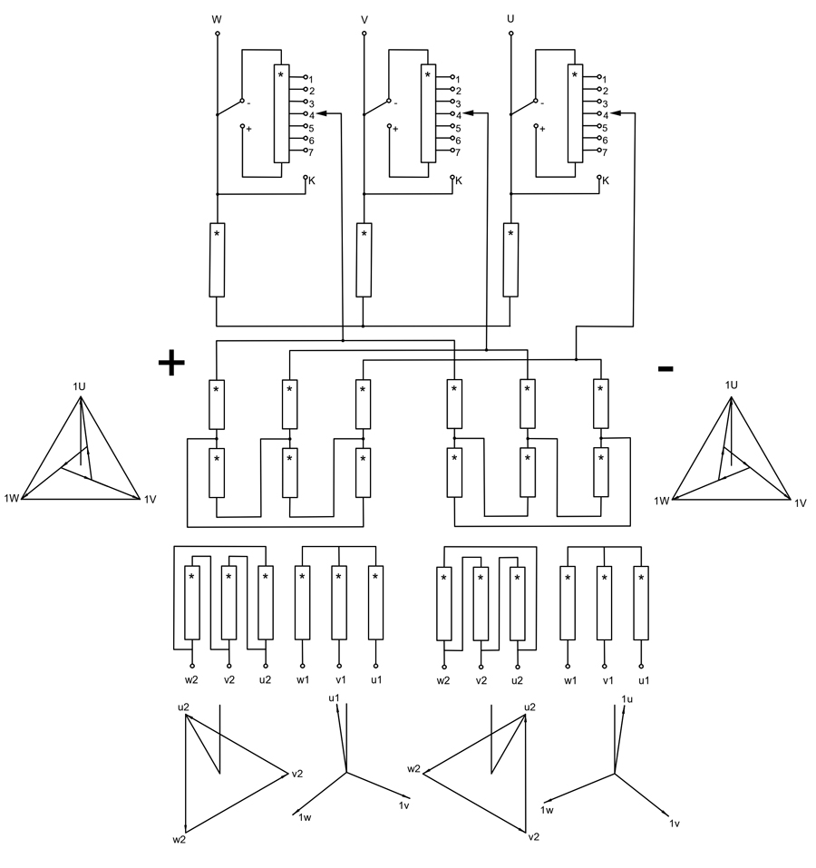
The configurations for a 24-pulse rectifier transformer, which includes the phase-shift transformers, have side-extended delta-connection primary windings and four secondary windings with conventional delta and Y connections, respectively. The unit used in this analysis incorporates automatic regulation with extended‑delta windings connected in parallel and phase‑shifted on the primary side, along with four secondary star–delta outputs.
A traditional 24-pulse rectifier transformer uses two 12-pulse, phase-shifting rectifier transformers to form a 24-pulse rectifier to eliminate most of the harmonics on the grid side, as shown in Figure 1. Nevertheless, the large footprint of two transformers affects the layout of other equipment in the system. Considering the limited physical size of available space in prefabricated substations, a new 24-pulse rectifier transformer can realize a special phase-shifting angle by using a delta-extended connection, which can improve efficiency and greatly reduce the size of the area.
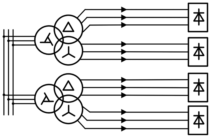
SOURCE: REPRODUCED FROM M. WANG ET AL. UNDER OPEN ACCESS CC BY 3.0 LICENSE.
Multi-pulse configurations
The most common designs include 12-pulse, 24-pulse, 48-pulse, and even 96-pulse systems. For example, a 96-pulse transformer (e.g., CEEG’s ZHSFT series) uses multiple parallel bridges with phase-shifted windings to reduce total harmonic distortion (THD) to below 10%, ensuring grid compatibility and protecting electrolyzers from voltage ripple.
High Efficiency
Modern transformers achieve efficiencies of 97.5% or higher at full load, minimizing energy waste. This is enabled by low-loss core materials (e.g., grain-oriented silicon steel) and optimized winding designs.
Precise Regulation
Combines on-load tap changers (OLTC) for coarse voltage adjustment (±10% stepwise) and thyristor phase-angle control for fine-tuning (continuous 0–100% output adjustability). This hybrid system ensures seamless adaptation to dynamic process requirements, such as changes in electrolyte concentration or production demand.
Multi-Winding Designs
One purpose of a multi-winding rectifier transformer is to minimize the harmonics injected into the grid. This is achieved by using rectifiers with higher pulse numbers (most commonly 12-pulse, 18-pulse, 24-pulse, 30-pulse, or 36-pulse) in combination with a corresponding phase-shifting input transformer. This means that the rectifier transformer has multiple secondary windings with relative phase displacement. Such phase shifting helps to eliminate certain harmonics from the spectrum seen on the primary side of the transformer. Generally, the higher the rectifier pulse number, the more the lower-order harmonics can be eliminated or minimized.
Classical Winding Connections
The smallest phase shift between windings is 30 degrees. This unit is called ”one hour’’ in clock notation. Such a phase shift is suitable for a 12-pulse system, i.e., a three-winding transformer with two secondary windings phase-shifted 30 degrees. Vector groups include Yy0d1, Dd0y11, etc.
For the rectifier to achieve a higher pulse number with less harmonic distortion, these additional winding connections are necessary: zig-zag (denoted as Z), extended delta, and polygon delta.
These winding connections allow phase shifts smaller than 30 degrees to be achieved. Theoretically, an arbitrarily small phase shift can be achieved, but factors such as manufacturing tolerances, cost, and overall complexity set the practical limits.
The configuration for the case under analysis is shown in Figure 2.
Voltage rating: 12.5 kV /526 V
Power rating: 6630 kVA
Frequency: 60 Hz.
Number of phases: 3
Type: ZHSZ-6630/12.5
Vector Group: Ya0 + DE/dy – DE/dy
LIMITATIONS OF CONVENTIONAL TTR TESTING
Conventional TTR methods assume symmetrical three-phase windings with direct phase correspondence. Due to the internal connections and phase displacement present in converter transformers, direct phase-to-phase ratio measurements produce misleading results.
TTR testers automatically perform ratio measurements, along with excitation‑current and phase‑shift measurements. These instruments carry out the turns‑ratio test phase by phase, short‑circuiting the adjacent phases not involved in the measurement, as recommended by transformer standards.
Testing a three‑phase rectifier transformer with non‑conventional vector groups and a wide variety of winding configurations is significantly more complex. These designs often involve phase mixing and shared magnetic cores; for example, half of the winding on core U may be energized from phase V, and so on. Such characteristics greatly complicate the algorithms required for automatic testing.
When the phase displacement between the line-side and rectifier-side voltages is not a multiple of 30 degrees, the simplest method is to perform the measurement using modern TTR instruments that now include direct menu options for ratio, excitation‑current, and phase‑shift measurements tailored to these unconventional vector groups. If this instrument is not available, then use IEC 61378-1, Converter Transformers.
TEST PRINCIPLE AND METHODOLOGY
IEC 61378-1 specifies a single-phase excitation method with cyclic permutation of the high-voltage phases. During each measurement, one HV phase is energized while the remaining two are short-circuited, and the induced voltage is measured on the corresponding low-voltage phase.
Voltage Ratio Reconstruction
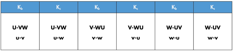
For each phase, two coefficients (Kb and Kc) are obtained. The effective voltage ratio is reconstructed using the IEC-defined analytical expression that compensates for phase displacement and magnetic coupling effects.
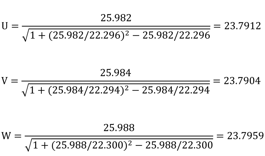
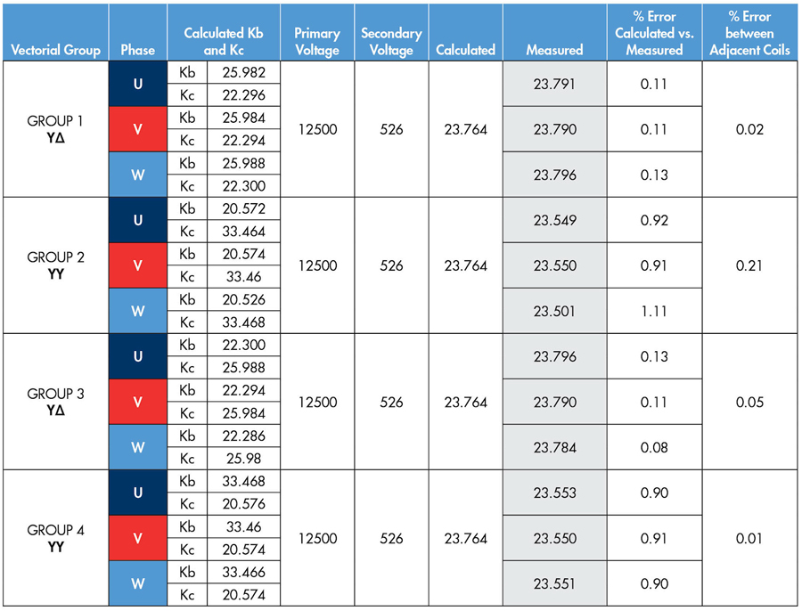
Field TTR tests were performed using a single-phase cyclic permutation method. The values Kb and Kc (the average of the three measurements) are used in the following equation for the effective voltage ratio:

where Kb and Kc are the averaged ratios obtained from cyclic permutation single-phase measurements.
This equation compensates for internal winding geometry and phase displacement inherent to rectifier transformers.
The turn ratio measurements should be performed in the single-phase configuration, feeding the HV phase (U, V, W) using a cyclic permutation with the other two phases short-circuited, against the respective LV phase (u, v, w) according to the following combinations (Table 1):
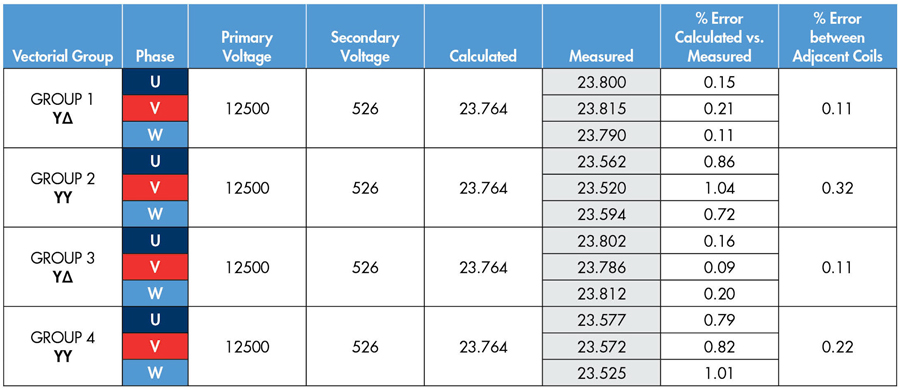
TEST RESULTS AND INTERPRETATION
Measured ratios were reconstructed using the IEC analytical formula and compared against calculated nominal values. Phase-to-phase deviations remained within acceptable IEC limits, confirming winding symmetry and correct tap configuration.
ACCEPTANCE CRITERIA
Typical acceptance limits for converter transformers specify that the ratio tolerance shall be within ±1.0%. In addition, IEEE Std. C57.18.10, IEEE Standard Practices and Requirements for Semiconductor Power Rectifier Transformers, establishes that the allowable tolerance for phase angle displacement is ±1 degree, and the voltage ratio tolerance is ±1%, unless otherwise specified.
Furthermore, the acceptance evaluation may also reference the requirements defined in ANSI/NETA ATS–2025, Standard for Acceptance Testing Specifications for Electrical Power Equipment and Systems, and ANSI/NETA MTS–2023, Standard for Maintenance Testing Specifications for Electrical Power Equipment and Systems, as applicable. These standards provide additional guidance for field testing, measurement practices, and performance assessment to ensure that the transformer meets operational and reliability expectations under actual service conditions.
CONCLUSIONS
The comparison between field and factory TTR results demonstrates a strong correlation when the IEC 61378-1 single-phase cyclic permutation method is correctly applied. The results validate field TTR testing as a reliable commissioning and condition assessment tool for 24-pulse rectifier transformers.
Beyond numerical correlation, this case study highlights the practical advantages of applying IEC 61378-1 test methodology during field testing. The cyclic permutation approach compensates for internal winding geometry, phase displacement, and complex vector groups commonly found in converter transformers, which are not adequately addressed by conventional three-phase TTR methods. As a result, testing personnel can obtain meaningful and repeatable measurements without relying on calculated or inferred ratios.
From a commissioning and maintenance perspective, the ability to directly compare field measurements with factory acceptance test data at the same tap position provides a high level of confidence in transformer integrity. This methodology allows early detection of winding issues, tap-changer discrepancies, or connection errors before energization, thereby reducing operational risk and unplanned outages.
Additionally, the methodology discussed here is not limited to the specific vector group evaluated. The same principles can be applied to transformers with star (Y), delta (D), extended delta, polygon, and other phase-shifting connections, regardless of whether the phase-shifting winding is located on the regulating or rectifier side. This flexibility makes the single-phase cyclic permutation method a valuable and broadly applicable tool for testing technicians working with converter transformers in industrial environments.
As shown in Figure 3, the average TTR values measured in the field closely match the corresponding factory acceptance test results across all connection groups, with deviations remaining well within acceptable limits. This comparison confirms the reliability and repeatability of the single-phase cyclic permutation method when applied during field testing.
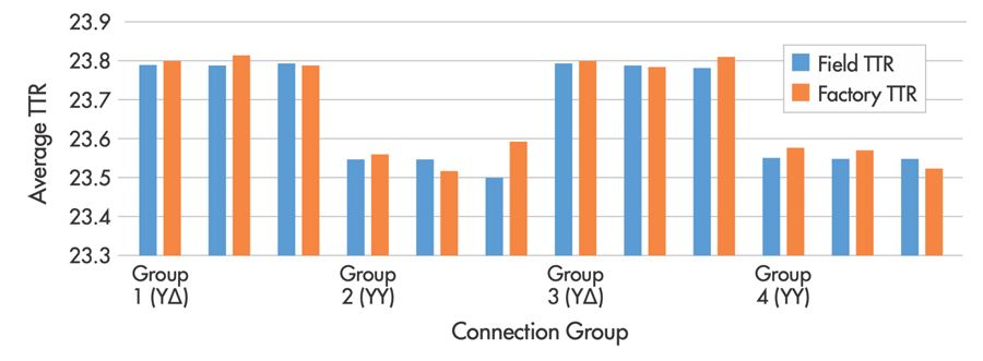
This chart compares average transformer turns ratio (TTR) values measured during field commissioning and factory acceptance testing for YΔ and YY connection groups at Tap Position #1.
REFERENCES
IEC 61378-1, Converter Transformers, Part 1: Transformers for Industrial Applications, Annex H.
IEEE C57.18.10-2021, IEEE Standard Practices and Requirements for Semiconductor Power Rectifier Transformers.
S. G. Jeyaraj, R. Milne, and G. Mitchell. “On-Site Testing of Special Transformers,” 10th IET International Conference on AC and DC Power Transmission (ACDC 2012), Birmingham, UK, 2012, pp. 1-6.
Mengxia Wang, Yong Li, Bonan An, Longfu Luo, Pencheng Wang, and Lin Gang. (2019). “A New 24-Pulse Rectifier Transformer with Delta-extended Connection,” IOP Conference Series: Earth and Environmental Science. NOTE: This is an Open Access work distributed under the Creative Commons Attribution (CC BY 3.0) license.
Der Chun Shih, Ling-Chung Hung, and Chun Ming Young. “The Harmonic Elimination Strategy for a 24-Pulse Converter with Unequal-Impedance Phase-Shift Transformers,” 2013 1st International Future Energy Electronics Conference (IFEEC), Tainan, Taiwan, 2013, pp. 783–788.

Erik Marin is a Field Engineer for Saber Power Services, LLC. He is a NETA Level IV Senior Technician with more than 15 years of experience in electrical power systems, maintenance, and field diagnostics. His expertise includes acceptance and maintenance testing of medium- and high-voltage equipment such as power transformers, switchgear, circuit breakers, control systems, and grounding systems in accordance with NETA, IEEE, and IEC standards. He previously worked as an Electrical Distribution Superintendent at Petróleos de Venezuela (PDVSA), where he oversaw electrical distribution operations and maintenance programs for substations and oil-production facilities. Marin holds a BS in Electrical Engineering from the University of Zulia in Maracaibo, Venezuela, evaluated in the United States as equivalent to a regionally accredited engineering degree.