
Power infrastructure failure is a common challenge across commercial, industrial, and utility sites. Failure of the underlying power system can lead to unplanned outages and equipment damage, so the benefits of prevention far outweigh the consequences of failures.
It is important to evaluate the health of a facility’s power system. Following the industry-recognized maintenance practices in NFPA 70B®, Standard for Electrical Equipment Maintenance®, and ANSI/NETA MTS, Standard for Maintenance Testing Specifications for Electrical Power Equipment and Systems, can serve as an early warning system for potential upcoming failures.
This is where power equipment modernization comes into play. By actively evaluating a power system and mitigating the risks posed by aging or failing equipment, it is possible to bring a power system up to current standards, use the newest technologies in protection and control, improve personnel safety, and greatly increase the reliability and lifespan of the equipment, thereby reducing maintenance and operation costs over the life of the equipment. Since a facility’s electrical system forms the backbone of critical operations, modernization is not an option; it is a necessity.
There are many approaches to modernization, and this article explores the risks associated with keeping aging or damaged equipment in service, as well as specific methods of modernization, including the benefits, use cases, and technical considerations of each method.
IDENTIFYING THE NEED FOR MODERNIZATION
The first point of discussion is the need for modernization and the risk factors that should be identified and prioritized. Equipment that has had significant exposure to a harsh environment, has been damaged, or has a negative test report indicating an item of concern should all be considered when determining whether equipment needs to be modernized.
Problem
Equipment exposed to a harsh environment, such as in a facility that processes corrosive chemicals or in high humidity areas, should be regularly evaluated for signs of corrosion and should undergo a more frequent maintenance cycle. Corrosion can have a negative impact on the structural integrity of switchgear, causing moisture buildup inside the equipment and corrosion on current-carrying components such as hardware on a busbar joint or cable connection, and leading to increased temperatures and thermal failures emdash or even arc flash. Humidity can also damage sensitive electronics, leading to device failure, which in turn can lead to mis-operation or non-operation of a circuit breaker.
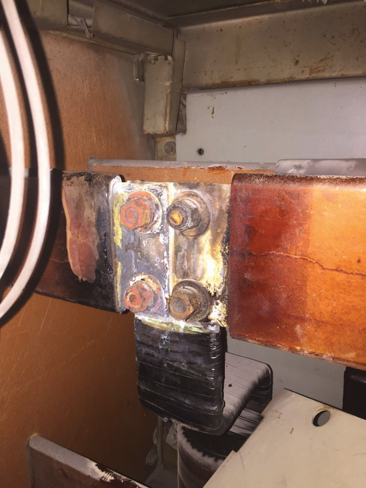
Internal damage to switchgear is a sure sign of a problem, including tracking seen on insulating components (Figure 1), burned or melted insulators, discolored conductors (Figure 2), pitting or erosion of conductors, and more. Many of these hazards hide inside switchgear and only come to light during infrequent outages, or when the equipment itself experiences dielectric failure or a thermal event.
Regular maintenance and testing, and a thorough review of the test results, can do a good job of predicting when a piece of equipment is at risk. Common indicators include changes to breaker trip time or breaker mis-operation, poor transformer oil sample results pointing to insulation failure, or failure of a relay to produce a proper trip signal when secondary injection testing is performed. In each of these cases, it is time to evaluate options for replacing the failed equipment.
When these risks go undetected, the outcome of a failure is almost always the same: an unplanned outage and emergency recovery. Many of these failures can lead to arc flash events or cause significant property damage. Recovery from an unplanned outage can be costly and take a long time, negatively impacting production and increasing operating costs. If personnel are present during an event, there is also a significant safety risk due to the hazards of electrical shock and incident energy released during an arc flash.

Solutions
With the problem established, solutions can be evaluated. Full equipment replacement is almost always an option, but it can be costly and require a significant amount of time to complete. In a time of ever-extending lead times, it is not unrealistic to wait more than a year for new switchgear.
This is where modernization can truly shine. The core of modernization is this: Leave what is good and upgrade the rest. Looking at another definition, taken from IEEE Std. C37.59–2018, IEEE Standard for Requirements for Conversion of Power Switchgear Equipment, conversion is defined in Chapter 3 as:
the process of altering existing power switchgear equipment from any qualified design.
Modernizing power equipment follows the process laid out in this standard: Keep existing qualified equipment and alter it using modern technology. This can mean leaving the wiring in place when replacing a protective relay or leaving the bus and sheet metal in place and replacing an obsolete circuit breaker.
When considering these options, it should be noted that standards have been established for this type of work. Vendors who perform this work must understand the standards for the equipment they are modifying, as installations that do not meet the minimum design requirements or have not undergone the required rigorous testing can put an entire facility at risk. IEEE C37.59 is one such standard, along with the type-specific standards established by IEEE and other standards organizations.
MODERNIZATION CASES
Two common use cases of modernization are presented here: protective relay upgrades and circuit breaker retrofills. These are by no means the only methods to consider, but they are good solutions to common problems found in aging equipment.
Protective Relay Upgrades
Protective relays have come a long way since their initial development over 100 years ago. The relays that were installed in much of the industrial world through the 1950s and 1960s were electromechanical relays — single-function devices such as a single phase 50/51 overcurrent protection relay, although many other purpose-driven devices existed as well.
Electromechanical relays continued to be used even after digital protection relays were developed in the 1970s, and many of those relays can be found protecting equipment today.
Electromechanical relays have stood the test of time, but they present many challenges in the modern world. For example, these devices can be sensitive to physical movement, sending inadvertent trip signals sometimes triggered just by opening or closing a compartment door.
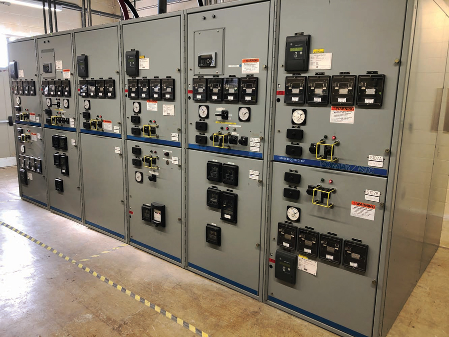
They also have limited functionality. For example, if a three-phase system required both overcurrent protection and undervoltage protection on each phase, then six separate relays were required. The space required for these devices often led to additional control cabinets installed across switchgear aisles or on top of a section of switchgear, consuming floor space that could be used for other equipment (Figure 4).
Using multiple devices also leads to additional points of failure and additional components to test and evaluate, extending the duration of maintenance outages. Aside from the physical constraints, there are also capability constraints. While technology has improved to include more complex monitoring, control, and communications systems, electromechanical relays have remained the same, and they cannot be integrated into these systems.
One solution is to modernize electromechanical relays to microprocessor-based relays. Microprocessor relays provide expanded protection and metering capabilities, and integration into existing SCADA and building automation systems. The modernization process is straightforward. First, a minimal outage is required to verify existing wiring and all connections to the existing devices. Once design and in-shop assembly and testing are completed, a new relay door can be installed during another short-duration outage (Figure 5). Some manufacturers offer kits that act as a direct replacement for obsolete relays, further reducing the required downtime for replacement.

The benefits of upgrading to modern protective relays are extensive. The key benefit is the extended service life that comes with updating the equipment. Once a relay has been upgraded, it should not need replacement again for more than 20 years if properly maintained. Modern relays also have added functionality that allows for improved device coordination and reduction of arc-flash risk through the addition of light detection, working in conjunction with current sensing and logic. They also provide multiple protection elements, which can reduce the overall number of relays that require maintenance.
Beyond these benefits, the ability to implement logic calculations and communications allows more complex protection and automation schemes to be implemented and integrated into building automation and SCADA systems.
Circuit Breaker Retrofills
Another modernization method is to perform circuit breaker retrofills in low- and medium-voltage switchgear. But first, there is some history to discuss.
The use of electricity introduces risks of damage to equipment and harm to those operating electrically powered equipment. With the need for protection from these risks, Thomas Edison developed early devices using fuses as the protective element, and fuses are still used for the same purpose. While there is a place for using fuses, there are also drawbacks, such as the need to replace them each time they operate.
The need for improved operation drove innovation that led to the development of what we now know as the modern circuit breaker. Early devices used the thermal-magnetic properties of bi-metals to force the circuit breaker contacts open, using air as an insulator to extinguish the arc between the contacts. As voltage and current requirements increased, these breakers had to be larger to handle the added load and interrupt current, and air alone was eventually not a sufficient insulator to extinguish the arc. This led to the introduction of insulation mediums to extinguish the arc, including oil, SF6 gas, and eventually a vacuum-encapsulated contact, which is now widely used in medium-voltage power distribution.
Technology also improved for low-voltage circuit breakers, moving far beyond the capabilities of the thermal-magnetic breaker, which had limited capability for adjustments. Oil dashpots were one early invention that allowed a delay to be introduced. Later innovations in electronics eventually led to electronic trip units that, like a protective relay, support a broad range of adjustments, improving breaker coordination and safety and reducing the risk of arc-flash.
With the rapid rise in the need for electricity and rapid improvement in technology, a significant number of circuit breakers have been installed using obsolete technology. Even with proper maintenance, devices installed in the 1960s are well beyond their expected lifecycle, putting an electrical system at risk. Continued use will lead to worn or fused contacts, tracking in insulation, oil and gas leaks, and more.
A common challenge is how to handle the replacement of these devices as a preventive measure or in response to failure. While full switchgear replacement is a consideration, the costs of this type of replacement can be extensive. It can also be challenging to move equipment into and out of a building that has been built around an electrical room, and the required downtime for a full replacement may not be reasonable. In these situations, a circuit breaker retrofill is a good option.
While the circuit breaker may experience failure or not meet modern requirements, the switchgear that contains it may not have the same issues. The copper, aluminum, and steel used in switchgear construction have not seen the same changes as the functional components of circuit breakers and can often be left in place and reused when the older circuit breaker is removed.
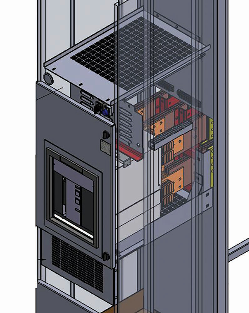
The process for a retrofill, like a relay replacement, begins with data collection. A site visit is performed to thoroughly inspect the switchgear and collect the required data for the design and installation of a new breaker during a planned outage. These details include nameplate data of the switchgear and breaker, detailed dimensional information for the construction, and a thorough evaluation of switchgear components. Those details are fed into the design, where the appropriate circuit breaker is specified, and components are designed to integrate the new breaker (Figure 6).
New components typically involve copper busbar conductors and sheet metal or insulating material structural members and barriers. The new components are specifically designed to meet the established standards for current-carrying capacity and short-circuit withstand capability. In some cases, these designs can be completed without type testing, but the best practice (and required practice for most IEEE standards) is to qualify a standard design by performing short-circuit and heat-rise testing. Using a qualified design ensures that the new installation can withstand the extreme forces and high currents of a short-circuit event and safely operate under normal circumstances without overheating. Once the design is complete and materials are fabricated, the installation can be scheduled. A retrofill of a single low-voltage circuit breaker can generally be completed in less than two days, compared to much longer installation time for a new section of switchgear. With the retrofill completed, a new circuit breaker with modern technology and little or no expanded footprint has been installed without tearing out a full section of switchgear.
FINAL CONSIDERATIONS
Modern technology has resulted in significant improvements in power distribution. Beyond relays and circuit breakers, other new devices, such as arc quenching devices and light-based arc flash monitors, reduce the risks associated with arc flash, and thermal sensors can actively monitor potential hot spots.
Constant innovations in this field regularly lead to new technologies to improve safety and reliability. While improving one area, additional solutions can be installed, creating an even more robust electrical system. The reasons to consider modernization can include cost, the need to improve capacity, safety, or more. In the end, modernization results in a more robust and reliable electrical system, renewing the life of the equipment it contains and reducing the risk of injury to personnel operating it.
Modernization is more than responding to aging infrastructure. It is a proactive investment in reliability, safety, and efficiency. Facilities that prioritize modernization position themselves to meet today’s demands and tomorrow’s challenges with confidence.

Seth Kravetz, PE, is an Engineering Manager at Qualus, specializing in electrical modernization. He began his career designing modernization solutions for power equipment before moving into his current role. He now leads a team of engineers who help clients improve system reliability and safety. Seth shares his expertise through client education, technical papers, and conference presentations. He holds a BS in electrical engineering from the University of Kentucky.