

The days of low-voltage breakers being simple devices with basic overcurrent protection are long gone. Back then, the biggest challenge was to figure out how to defeat a ground fault or remember which jumper disabled thermal memory. Today, manufacturers are leveraging digital technology to add layers of protection and functionality. These advancements can quickly derail a routine day of testing if you’re not prepared. The key is to study the manuals, share lessons learned, and stay familiar with new features.
COMPLEX LOW-VOLTAGE BREAKERS
This article highlights common challenges and lessons from the field so the next technician doesn’t have to learn them the hard way.
Complex Controls
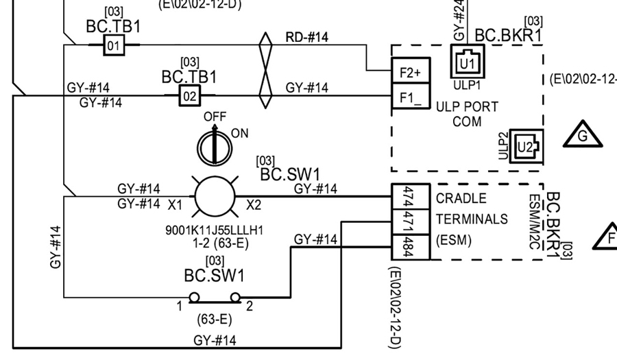
What used to be straightforward control circuits have become increasingly complex. The control drawing in Figure 1 may look like it came from a medium-voltage lineup, but it’s actually for a 208-V feeder breaker.

These drawings document the entire control system. From auxiliary contacts for status lights to zone selective interlocking (ZSI), and everything in between, these drawings are essential for proper acceptance testing and troubleshooting. For reliable operation, these circuits must be functionally tested — not just assumed correct.
The catch is that this level of control complexity is seldom recognized during bidding or early project planning. Estimators, project managers, and technicians must budget time for these verifications. Competitors who skip this scope may undercut pricing but deliver incomplete testing. Make it your role to educate clients on the risks and the value of thorough functional checks.
Pro Tip: Review control drawings before mobilizing. For example, the ERMS excerpts in Figure 2 and Figure 3 show connection points and power requirements. Having this knowledge upfront allows you to develop effective methods of procedure (MOPs) and avoid surprises on-site.
Note: ERMS is off with the switch closed.

Note: ERMS is off with the switch open.
Ground Fault Defeat
Ground-fault protection has been standard for decades, but it still causes headaches. For legacy trip units, many of us have relied on cheat sheets to remember the right method, whether it’s installing a jumper, moving a neutral lead, or using the proper secondary test set.
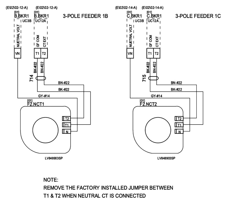
With today’s modern trip units, it is more critical to ensure that you have the correct software to allow for ground fault defeat. Those who have found themselves in the field downloading software tell a story of frustration. Reviewing drawings ahead of time also ensures you’re ready for the required primary current tests — trip and no-trip of the ground fault system — which confirms proper CT orientation and wiring. Figure 4 illustrates the neutral CT connections and provides a note about removing a factory-installed jumper. The devil is in the details.
Zone Selective Interlocking
ZSI has been around for years. It allows downstream devices to clear faults while signaling upstream breakers to delay tripping. If the upstream breaker doesn’t receive that signal, it trips faster to clear the fault.
During testing, technicians must simulate this input to verify proper time-delay operation per the manufacturer’s trip curves. This is often as simple as installing a jumper between the ZSI input. In Figure 5, note the jumper needed between Z3 and Z4.
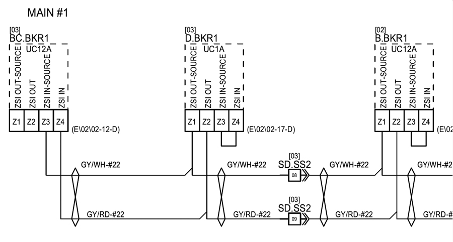
Pro Tip: Always confirm that ZSI asserts when a feeder fault occurs. Review drawings carefully, as shipping splits (circled in red in Figure 5) often reveal incomplete wiring. Some ZSI systems can be verified with manufacturer software, while others (like GE Entelliguard) require a dedicated test set.
SPECIFIC BREAKER CHALLENGES
Siemens WL Breakers with ETU Trip Units
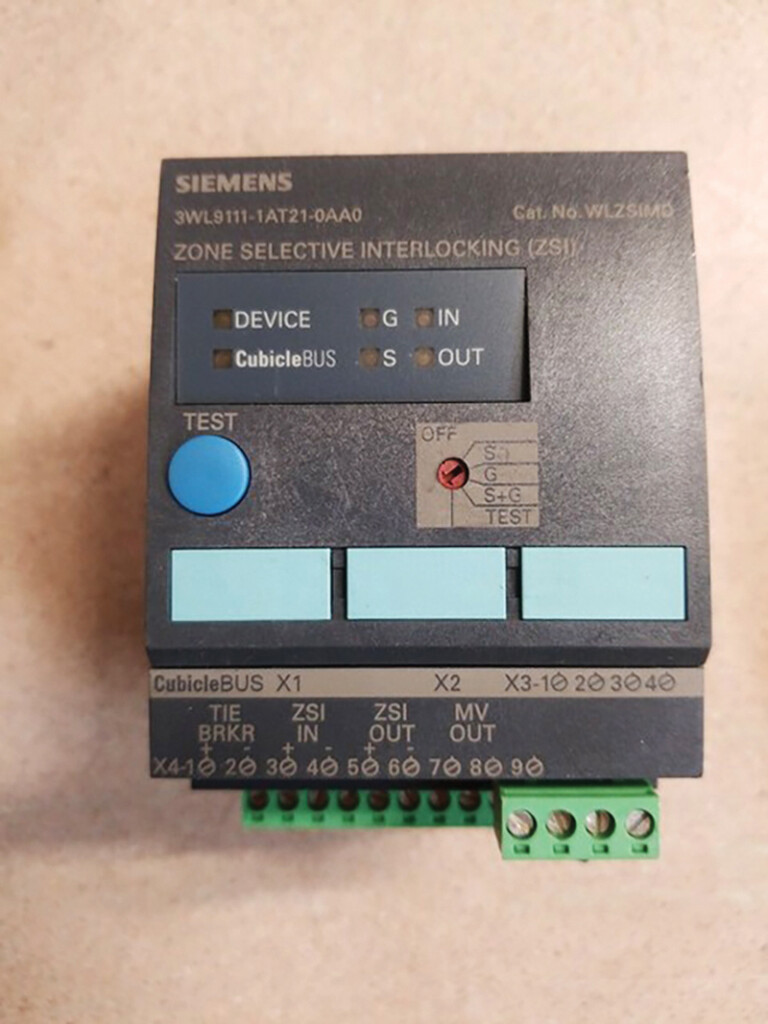
Siemens WL breakers with ETU trip units require ZSI to be deactivated before removing the breaker from its cell. If not, trip times default to instantaneous rather than the expected long-time delay. See Figure 6 for a picture of the device and plan accordingly to defeat ZSI.
We recently encountered phase-loss sensitivity on the ETU776(Figure 7). It’s hidden under protective parameters, but it can be disabled if you know where to look.
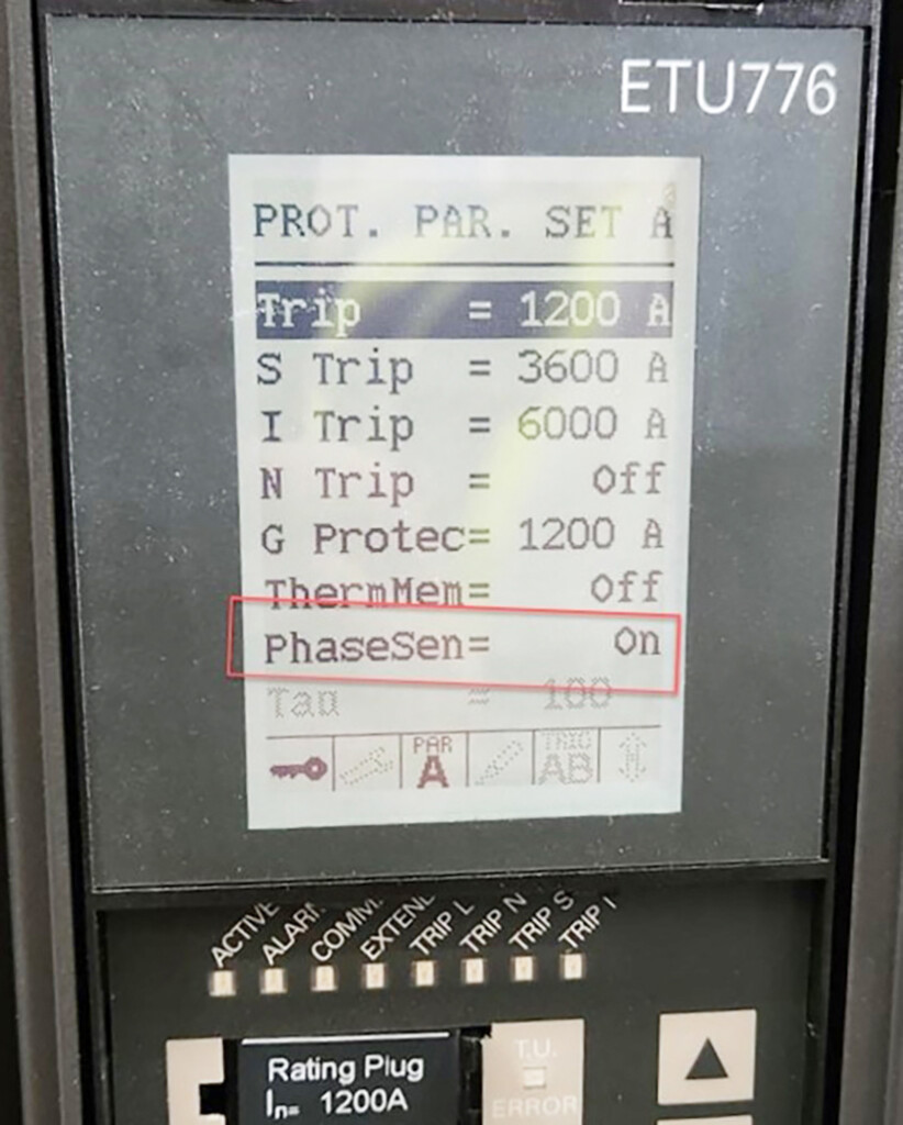
PHOTO COURTESY JOE GOSS
There is a catch, and it is in Siemens’ own literature and took some digging to find.
Phase Loss Sensitivity
When single-phase testing, make sure that the short-time delay is not set to the 20-ms setting. In this position, the phase-loss sensitivity function is enabled. This function is designed to protect motors from heavy imbalances and loss of one or more phases. When active, and the trip unit detects that the least heavily loaded phase is 50% lower than the most heavily loaded phase, the long-time pickup setting (IR) is reduced to 80% of the setting indicated on the display or dial. When this unbalance condition no longer exists, the setting is returned to normal. Single-phase testing will be recognized as a phase unbalance, and long-time trip timing will be faster than indicated in the trip curves. For an ETU776, phase-loss sensitivity is controlled by the PhaseSen menu item under the protective parameters. When a short-time delay is set to 20 ms, phase-loss sensitivity cannot be turned off.
Pro Tip: Ensure that Set A and Set B short-time delay parameters are above 20 ms to avoid phase-loss creating testing problems.
Schneider Masterpact MTZ with 6.0X Trip Units
On MTZ breakers with 6.0X trip units, ERMS can be disabled before removing the breaker as long as 24-VDC control power is applied and EcoStruxure software is available. If the breaker is pulled first, you’ll need a 24-VDC power supply and secondary plugs to power the trip unit outside the cell and then deactivate ERMS through software. See Figure 8 for a basic layout of the connections required.
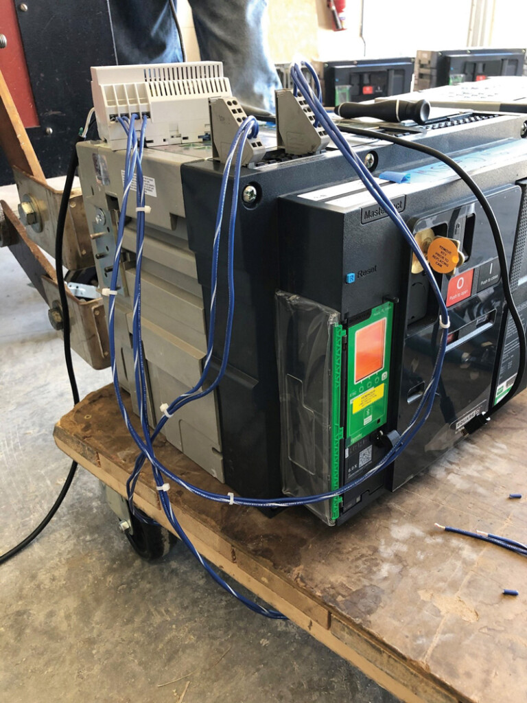
PHOTO COURTESY JESSE MASSMAN
Pro Tip: Build a dedicated kit for these various breaker types: Use a 24-VDC supply (most common, although some use 120 VAC), appropriate secondary plugs (don’t use a paper clip as seen in Figure 9), a cradle interlock defeat tool, and other tricks of the trade.

Pro-Tip: Use primary current connection plates of the correct thickness, which varies by manufacturer. To avoid breaker primary finger damage, ensure you are using the correct thickness. For example, for the MasterPact and LS Electric breakers, 3/8 inch is too thin; 1/2 inch is too thick.
Service Life of MTZ Breakers
At PowerTest25, panelists raised a question about MTZ breaker life expectancy. My follow-up research confirmed that MTZ breakers and their 6.0X trip units have a documented 15-year service life, though conditions play a big role. Many units in service today may already be a third of the way, or more, through their life span. End of life can be checked using EcoStruxure error codes (Table 1).

Table 1: Examples of MTX Breaker Error Codes
LS Electric Breakers
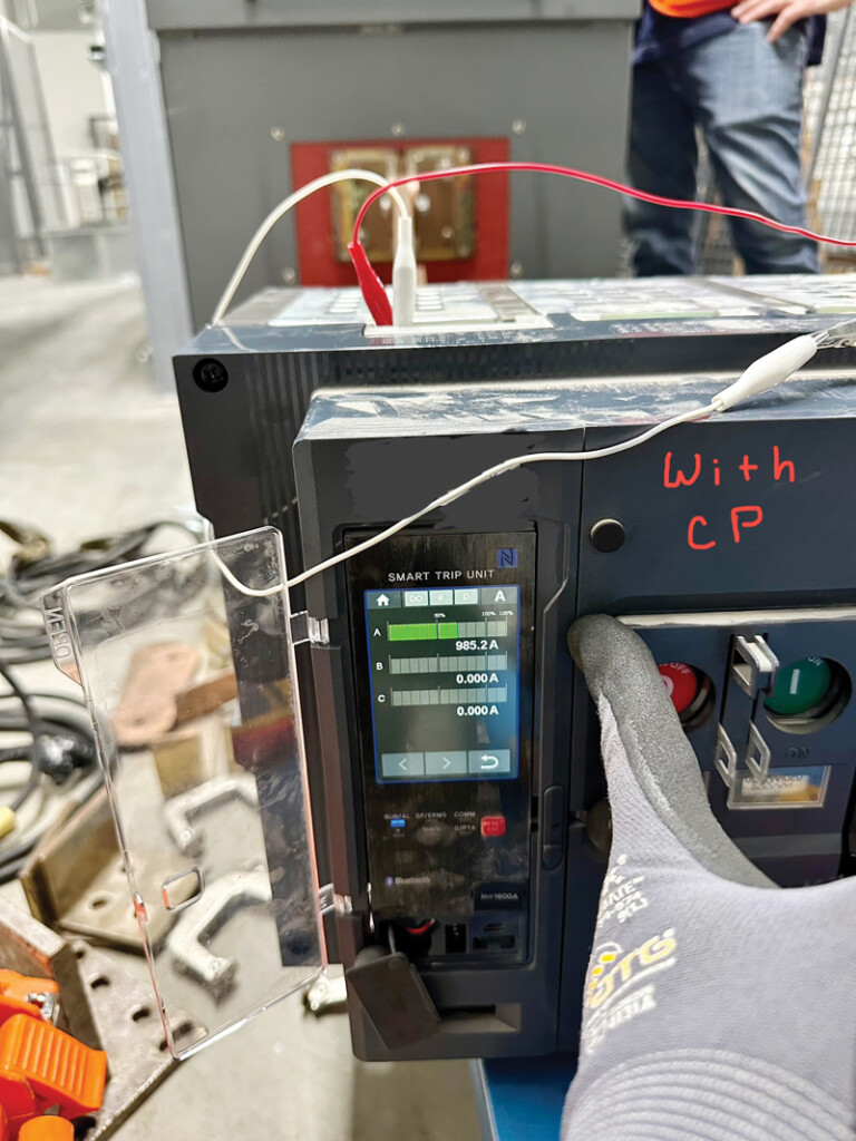
Our first encounter with LS Electric breakers came during a maintenance outage. The customer had secondary test sets for powering up the trip units and defeating ground faults. However, upon testing the first breaker, the trip unit displayed odd readings — about 30 amps (Figure 10) on all three phases during a 1000-amp single-phase test. After repeated failures, we contacted the manufacturer.

The issue: Not all LS Electric trip units are self-powered. Secondary test sets alone don’t provide proper control power. External control voltage must be applied to these units in the same way as a switchboard. Once we supplied 120-Vac control power, the breakers tested as expected (Figure 11).
Supportive information from LS Electric when power control is lost:
- The trip unit shuts down (will not power on).
- Protective functions may not operate, and the breaker may fail to trip.
- Long-term operation without control power may degrade the microcontroller.
LS Electric suggests three mitigations:
- UPS installation for critical loads
- UVT coil to force a trip on loss of control power. Not recommended for system reliability; imagine an entire substation going down for a blown control fuse.
- Alarm integration to alert operators to control power loss.
LS Electric does offer self-powered trip units. Users should confirm which model they’re ordering and how that impacts the system operation.
Insulation Resistance Testing
Many modern trip units include voltage sensing. Some older versions required pulling fuses or removing rating plugs. Eaton’s Power Defense line (PXR) now uses internal 6-MΩ resistors for metering. During insulation resistance tests, these low values will be noted. Having the manufacturer’s literature will save you time second-guessing yourself.
Pro Tip: If you see low readings that don’t meet the minimums in ANSI/NETA ATS and ANSI/NETA MTS, double-check yourself, document the results, and call the manufacturer’s rep before wasting time chasing a bad test.
FAILURES IN THE FIELD
Are failures more common now? Maybe, maybe not. But during recent acceptance testing of 800-A bolt-in breakers, three out of four failed to trip on A-phase during primary injection testing. Secondary injection showed that the trip units functioned properly and confirmed that the CTs were good.
At the manufacturer’s direction, the trip unit was installed in a new breaker. A-Phase still failed. The lesson learned, once the trip unit was removed: In this breaker/trip unit design, the CTs are integral to the trip unit. The other lesson is that secondary injection does not identify all trip unit issues. The red arrows in Figure 12 point to the CTs on the trip unit.
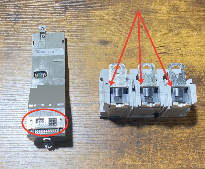
In contrast, a Micrologic 6.0 trip unit relies on CTs that are integral to the breaker and provide input to its processor via a plug connection(s) circled in red (Figure 12). This is an important distinction to understand when troubleshooting trip unit failures and corrective recommendations.
FINAL THOUGHTS
As technicians, we’re responsible for the safe and reliable operation of low-voltage power systems. Technology is moving fast, and our procedures must keep pace. Whether it’s interpreting control drawings, learning manufacturer software, or digging deep into manuals, we must commit to continuous learning.
Sharing lessons across companies and engaging manufacturers early saves time and minimizes frustration. One technician’s hard-earned experience can raise the competence of the entire NETA community. Hopefully, this article contributes to that effort.
Be safe, stay curious, and keep learning.

Mose Ramieh is Vice President of Business Development at CBS Field Services. A former Navy man, Texas Longhorn, Vlogger, CrossFit enthusiast, and slow-cigar-smoking champion, Ramieh has been in the electrical testing industry for more than 25 years. He is a Level IV NETA Certified Technician with an eye for simplicity and utilizing the KISS principle in the execution of acceptance and maintenance testing. Over the years, Ramieh has held positions ranging from field service technician, operations, sales, and business development to company owner. To this day, he claims he is on call 24/7/365 to assist anyone with an electrical challenge. That includes you, so be sure to connect with him on the socials.