
Modern numerical transformer protection relays have powerful logic to prevent unwanted tripping on phase differential during CT saturation for external faults. This article analyzes this logic for a typical application. To demonstrate these protection features, we will simulate the low-side fault current for an out-of-zone fault using the IEEE PSRC CT Saturation Calculator. Note that this type of exercise is never a substitute for properly sizing the CTs.
APPLICATION
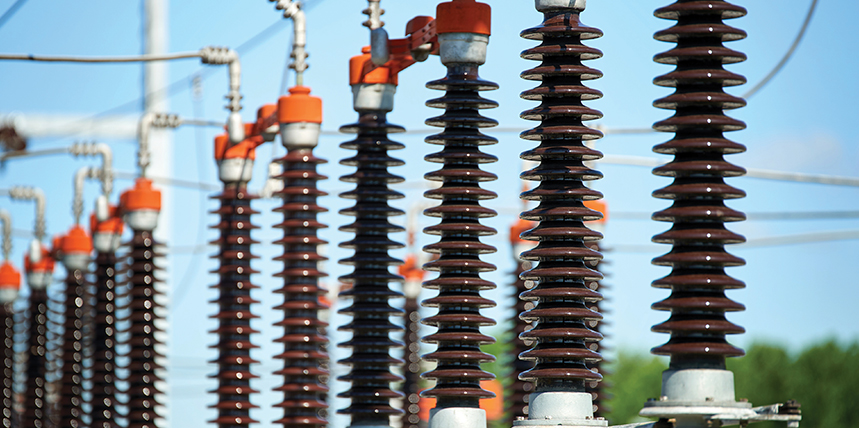
A contractor wants to use a C200 CT on the low side of a main transformer for a numerical differential protection application. The vendor can provide C400 CTs but prefers the C200 CTs at the MV SWGR main breaker due to space constraints.
The low-side asymmetrical fault current for an out-of-zone fault is simulated using the IEEE PSRC CT Saturation Calculator (see Appendix). The corresponding secondary current is analyzed using SynchroWave Event. The relay provides even harmonic blocking and restraint, as well as logic designed to prevent unwanted tripping during CT saturation for out-of-zone faults, which is also analyzed. The phase differential protection is considered secure if it operates only for in-zone faults.
IEEE CT SATURATION CALCULATOR INPUTS
The low-side C200 CT performance was evaluated for an out-of-zone, three-phase fault using the IEEE PSRC CT Saturation Calculator.
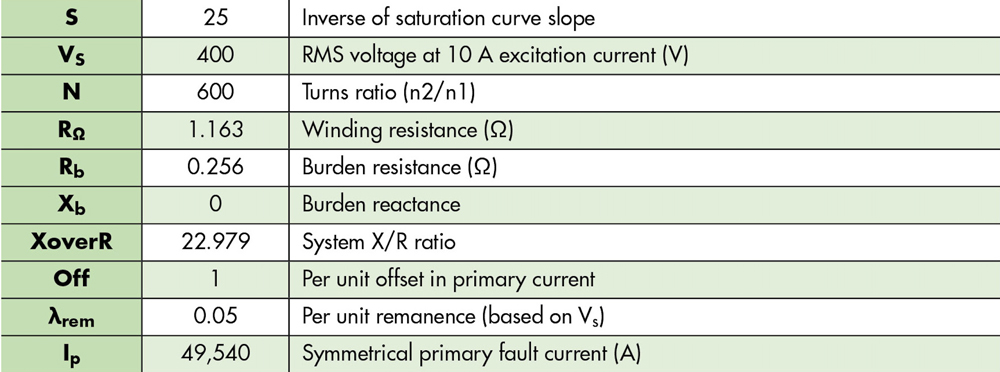
The saturation calculator models the CT secondary current based on fault current, system X/R ratio, saturation voltage of the CT, secondary winding resistance, CT burden, remnant flux, per-unit fault current offset, and the CT S curve slope. Note: The highlighted numbers throughout the article indicate input to the calculator.
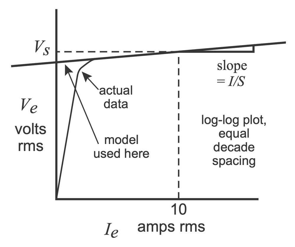
The straight-line curve with slope 1/S shown in Figure 1 is not linear. The curve is defined mathematically as:

Vi is the value of Ve for Ie equal to one amp; that is, log Ie equals zero. Resolving the logs yields:

Ve for an excitation current equal to one amp according to the C200 CT excitation curve is 210 volts. Vi is calculated for an excitation current equal to 10 amps, which yields the following value for S, solved iteratively:
370 * 101/S = 399.5
S = 25
RMS Voltage at 10 Amps Excitation Current
VS is determined by inspecting the C200 CT excitation curve:
VS = 400 V
CT Turns Ratio
N = 3000:5 = 600
CT Winding Resistance
The CT winding resistance is provided on the C200 CT excitation curve (62-400-066-XXX):
Rw = 1.163 Ω
Burden Resistance
The burden resistance consists of the relay current input and the leads to and from the CT:
Prelay = 0.5 VA @ 5 A (refer to page 1.14 of the SEL-487E instruction Manual Date Code 20240509)

X/R Ratio
The contractor stated: “The X/R ratio at guaranteed load losses (48 kW) is 18.974, and the ratio as expected losses after design (38 kW) is 22.979.”
DC Offset
Assume the worst case of a fully offset current waveform.
Per-Unit Remanence
Remanence is approximated closely by assuming the initial excitation curve is non-zero.
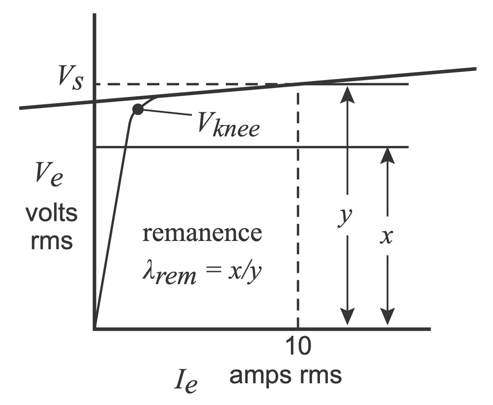
λrem is expressed in per unit of VS. To specify λrem accurately, specify x no greater than Vknee (see Figure 2).

(IBase is the transformer full-load current with respect to the low-side winding)
x/y = 0.047
Symmetrical Primary Fault Current

IF = (82.57 A) * (3000:5) = 49,536 A primary
SYNCHROWAVE EVENT INPUT
The saturated current waveform created by the IEEE CT Saturation Calculator is input to SynchroWAVE Event as a CSV file. The second harmonic content of the saturated current input is analyzed using calculations from Application Guide AG2024-11 and Custom Calculations in SynchroWave Event to Analyze Harmonic Signal Distortion.
RESULTS
CT Performance
The current begins to saturate at approximately 8.1 ms (0.49 cycles) following the low-side close-in, out-of-zone fault inception. There is saturation in both the positive and negative peaks, the former due to the DC offset and the latter due to the CT being undersized. The current is still saturated nine cycles following fault inception, which is the end of the simulation, as demonstrated in Figure 4A.

Second harmonic content is illustrated in Figure 4B. The content is calculated between the orange and magenta cursors. This period is slightly greater than one cycle. Harmonic blocking and restraint are activated based on the ratio of harmonic content present in the differential current versus the differential operate current per phase.

Relay Performance
- Harmonic blocking and restraint. The relay will block or restrain tripping on the differential due to even harmonic content in the measured current. The percentage of harmonic content is calculated based on the ratio of harmonic phase current versus the fundamental operating current per phase.
- External fault detection. The numerical transformer protection relay has logic designed to prevent unwanted tripping during CT saturation for out-of-zone faults. The relay distinguishes between external and internal faults by comparing the change in operating current (DIOP) to the change in restraint current (DIRT). If an external fault is detected, the operating mode switches to high security mode to help avoid a misoperation. Using high-security mode switches the differential characteristic changes from Slope 1 to Slope 2, and the security timer delay increases (Figure 5).

RECOMMENDATIONS
It is preferable to use the C400 CT since it has a higher saturation voltage and will not saturate as much as the C200 CT during external close-in low-side faults. The relay vendor stated: … a higher C-class rated CT is highly preferred.
Use the following settings to help mitigate unwanted tripping due to CT saturation during external close-in low-side faults:
Differential Element Configuration and Data
Enable harmonic blocking:
E87HB := Y *
Enable harmonic restraint:
E87HR := Y *
Set the 2nd harmonic percentage to 15%
PCT2 := 15
Set the 4th harmonic percentage to 15%
PCT4 := 15
Set Slope 1 to 35%:
SLP1 := 35.00
Set Slope 2 to 90%:
SLP1 := 90.00
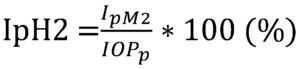
Note: Activating harmonic blocking and restraint is determined based on the ratio of harmonic content present in the differential current versus the differential operating current per phase. That is:
Where:
IpM2 = differential operating current per phase for the second harmonic
IOPp = fundamental differential operating current per phase
p = A, B, C
If the measured ratio is greater than the setting, then harmonic blocking and restraint are activated accordingly.
CONCLUSION
This article demonstrates how to analyze CT saturation using the IEEE PSRC CT Saturation Calculator (Figure 6 and Figure 7). Proper CTs with the correct C ratings should always be applied for transformer differential protection. Modern transformer protection relays have algorithms to account for CT saturation, but they are not a substitute for using properly rated CTs.
REFERENCES
- Schweitzer Engineering Laboratories. SEL-487E Instruction Manual, Date Code 20240509. Accessed at https://selinc.com/search/?term=SEL-487E+Instruction+Manual&ContentType=document.
- Schweitzer Engineering Laboratories. SELApplication Guide AG2024-11. Accessed at https://selinc.com/products/5601-2/.
- IEEE PSRC Committee. IEEE PSRC CT Saturation Calculator. https://electrical-engineering-portal.com/download-center/electrical-ms-excel-spreadsheets/ct-saturation-calculator
- Schweitzer Engineering Laboratories. SynchroWave Event. Accessed at https://selinc.com/search/?term=Custom+ Calculations+ in+SynchroWave+Event+to+ Analyze+Harmonic+Signal+Distortion.

Steve Turner is a Consultant at Sargent & Lundy. He was previously in charge of system protection for the Fossil Generation Department at Arizona Public Service Company for five years. Turner formerly held positions at Beckwith Electric Company, GEC Alstom, SEL, and Duke Energy, where he developed the first patent for double-ended fault location on overhead high-voltage transmission lines and was in charge of maintenance standards in the transmission department for protective relaying. He has BSEE and MSEE degrees from Virginia Tech University. Turner is an IEEE Senior Member and a member of the IEEE PSRC and has presented at numerous conferences.