

A low-voltage distribution system is the final stage of the electric grid. It is the infrastructure that moves electric power inside buildings and dwellings. Let’s define a low-voltage distribution system.
These systems rely on transformers (Figure 1) to step utility voltages down to usable levels. The most common voltages in such systems in the United States include 120, 240, 208, and 480 volts, depending on the type of service.
After the step-down transformer, electric power goes to a main service switchboard or panel, which distributes electric power throughout the building. Low-voltage electrical services are either single-phase or three-phase.
SINGLE-PHASE DISTRIBUTION SYSTEMS
240/120 (Split Phase)
When you see 240/120 listed on a transformer nameplate, it indicates a single 240-volt winding with a center tap (Figure 2). This is the low-voltage configuration on most single-phase pad-mount transformers. Here’s how it works.

You get the full 240-volt rating of the winding between X1 and X3. Because the X2 center tap splits the coil in half, the 240/120 setup is called “split phase.” This split-phase setup allows you to measure 120 volts between the line terminals and X2 (neutral). This winding type is perfect for serving single-phase systems with 240-volt and 120-volt loads.
120/240
When you see 120/240 marked on a transformer nameplate, it denotes two separate 120-volt coils set up to connect in either series or parallel (Figure 3).
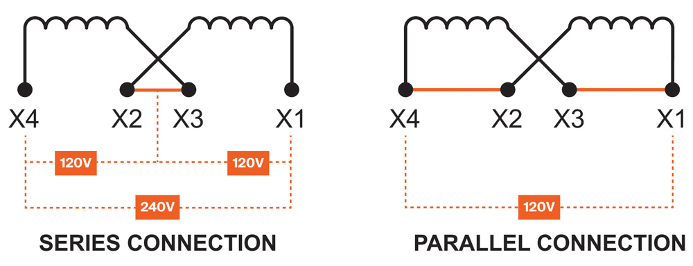
Series vs. Parallel Connections
In series, the coil voltages add to equal one total 240-volt winding (Figure 4). The point where the coils connect is the neutral point. The series connection mimics the split-phase 240/120 setup. In parallel, the voltage across both coils remains 120 volts.
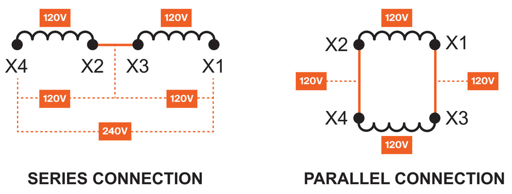
Most indoor single-phase applications include 240-volt and 120-volt loads. As a result, the series connection is more common. The parallel connection is more frequent with pole-mount transformers (Figure 5).

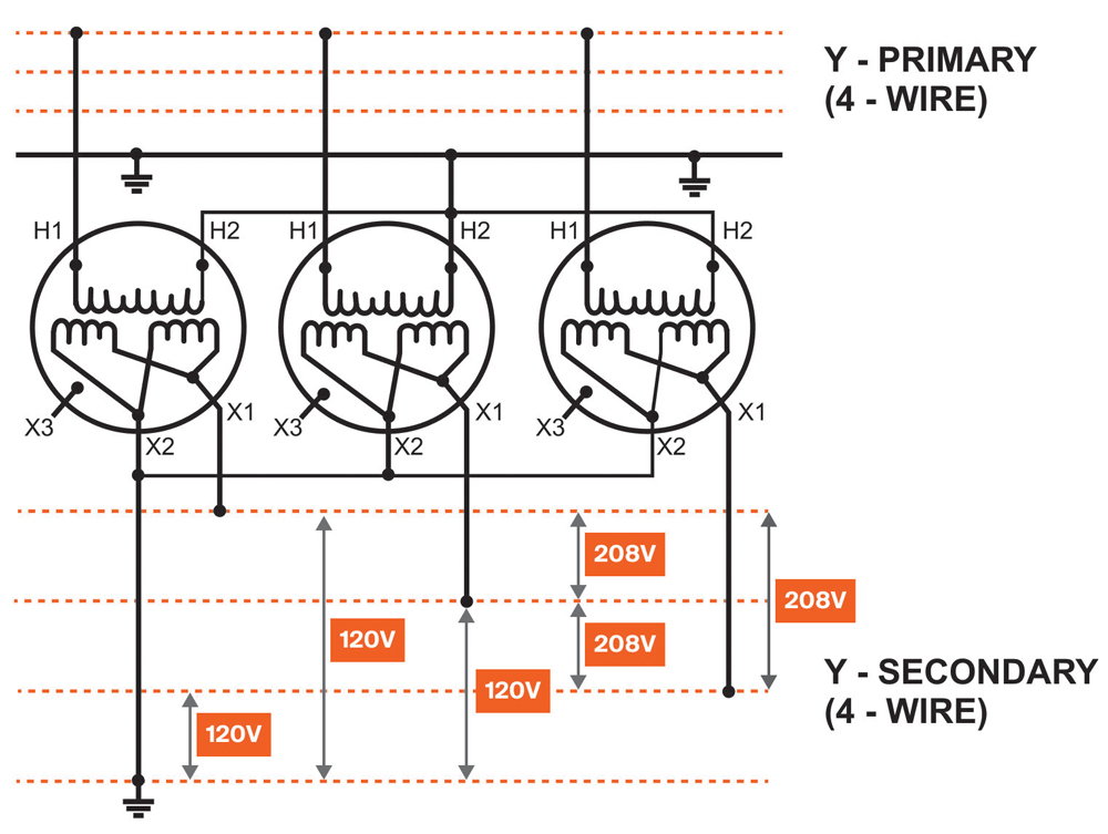
Figure 6 shows a single pole-mount with 120/240 windings in parallel. This configuration is the standard setup for three-phase pole-mount banks.

When connected with two other identical units (Figure 7), the result is a 208Y/120-V power supply.
THREE-PHRASE DISTRIBUTIONS SYSTEMS
Larger commercial and industrial buildings usually have three-phase distribution systems. The advantage of three-phase power is its larger loading capacity. It can also supply single-phase and three-phase loads.
Three-Wire System (3W)
Ungrounded systems will have a three-wire supply. In these systems, there is no grounded conductor (or neutral). The transformer winding supplying power has no intentional connection to Earth’s ground.
Four-Wire System (4W)
A four-wire system contains three ungrounded phase conductors and one neutral conductor. The bare copper safety ground is not counted as a current-carrying conductor. In a four-wire system, the neutral conductor (fourth wire) bonds to Earth’s ground. This system is the most common in newer facilities supplied with three-phase power.
240 V Delta
The three-phase delta system (Figure 8) is less common today. In this system, the line voltage and coil voltage are the same. Each phase measures 240 volts across each respective coil. This setup can supply 240-volt three-phase and single-phase power (Figure 9).


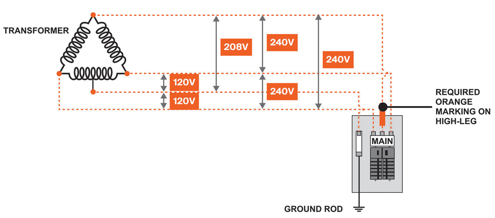
240-V Delta with 120-V Center Tap
Many 240-volt delta windings have a center tap on one of the three coils. This provides an option for a limited 120-volt output. This center tap, often called a “lighting tap,” supplies single-phase power for small lighting and receptacle loads. The coil with the center tap acts identically to the 240/120 single-phase scenario. The measurement between the center tap and adjacent phases is 120 volts. The measurement between the center tap and the opposite phase yields 208 volts.
The phase that measures 208 volts from the center tap (Figure 10) goes by many names: high leg, wild leg, stinger leg, etc. The high leg is very common in older delta supply systems in the US. This configuration works best for three-phase installations with minimal 120-volt needs. The amount of single-phase 120-volt loading should not exceed 5–10% of the supply transformer kVA.

240V Corner-Grounded Delta
In some cases, one phase of a delta winding may be solidly connected to Earth (ground). One of three normally ungrounded conductors will have a solid connection to Earth (Figure 11). The grounded phase must remain consistent throughout the system.

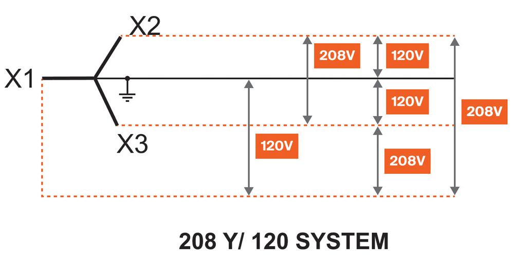
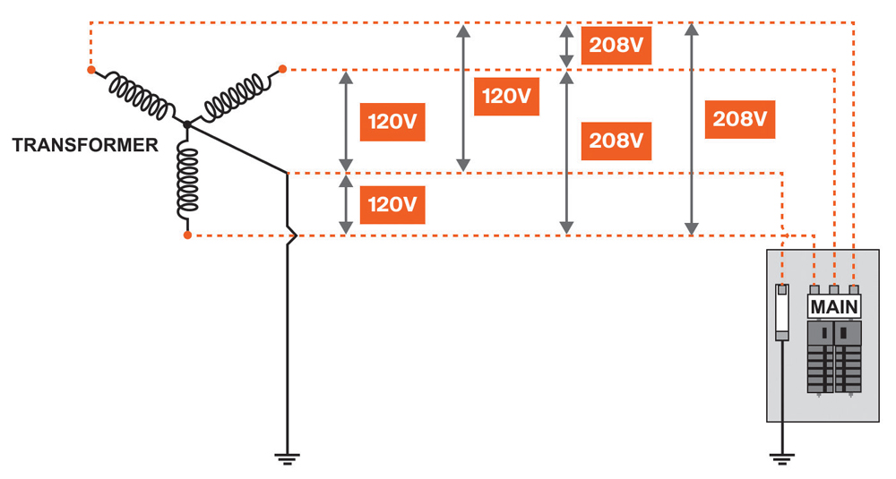
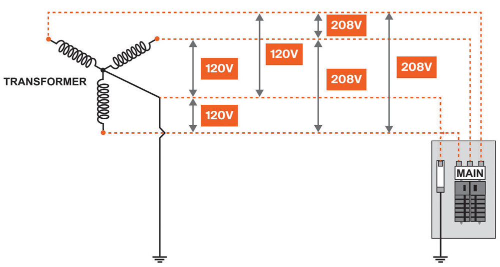
208 Y/ 120
208 Y/ 120 systems supply both 120-volt single-phase and 208-volt three-phase loads (Figure 12). This configuration is common for commercial establishments such as apartment buildings. In this setup, three-phase power runs larger equipment. The 120-volt supply serves single-phase loads such as lights, receptacles, and appliances. This system works best for buildings with larger 120-volt loads. The common neutral point allows balanced loading (unlike the high-leg delta system).
480 Y/ 277
Most industrial and large commercial buildings use a four-wire 480 Y/ 277 system (Figure 13). The 480 volts available from this system supplies both single-phase and three-phase needs. Single-phase lighting loads make use of the available 277 volts.

MEASURING SYSTEM VOLTAGE
The voltage between the ungrounded conductors in a system is the line voltage, also called phase-to-phase voltage (Figure 14). To determine the phase-to-phase voltage, test the voltage between A, B, and C phases at the main panel. This equates to measuring the voltage between H1, H2, and H3 or X1, X2, and X3 on a transformer. In Figure 14, the line voltage is 208 volts.
Measuring Line to Neutral
The voltage between the ungrounded and grounded conductor(s) in a system is the line to neutral voltage. In Figure 15, the line to neutral voltage is 120 volts. At the main service panel, measure between the neutral bus and the A, B, or C phase terminals.

Transformer wiring diagrams show the neutral point of the windings. On three-phase transformers, the high-voltage neutral is marked H0. The low-voltage neutral is marked X0. You will not find an H0 or X0 on single-phase transformers. The easiest way to identify the neutral point is by referring to the nameplate wiring diagram.
In three-phase, testing line to neutral measures one of three windings. In single-phase, testing line to neutral measures half of one winding.
Measuring Line to Ground
Line-to-ground measurements are sometimes misleading. A predictable measurement requires an intentional bond to Earth (ground). This bond is made at the source transformer neutral or first service disconnect. Redundant or faulty neutral-ground bonds will often obscure voltage readings. In a solidly grounded system, the line-to-ground and line-to-neutral voltages are the same.
Figure 16 shows a solidly grounded system. The neutral point of the source transformer bonds to Earth ground. The common bond causes the line-to-ground and line-to-neutral measurements to share the same value. In this example, the line-to-ground voltage is 120 volts.
Voltage readings line-to-ground vary for ungrounded systems. Examples of ungrounded systems include delta and ungrounded wye. In such cases, measurements may vary widely.
DELTA WINDINGS GROUNDED
240 Delta with 120 Center Tap Grounded
When the center tap of a delta winding is grounded, line-to-ground and line-to-neutral (center tap) values will match. Figure 17 shows the result of grounding the center tap of a delta winding. Line-to-ground values mimic the high-leg delta system described earlier. The center tap is normally marked on the transformer nameplate by an X4 or X6 terminal.
Pro Tip: Distinguishing between 208 Y/ 120 and 240 Delta High-Leg Systems
The high-leg delta system is sometimes mistaken for 208 Y/ 120. This is usually when only line-to-ground voltages are recorded at the service panel. The 208-volt reading across the center tap and high leg can be misleading. Remember, a 208 Y/ 120 system will measure the same voltage line-to-neutral between all phases. Avoid this problem by measuring the line-to-line voltage (240 volts) at the panel (instead of line-to-ground).
Corner-Grounded Delta
In a corner-grounded system, the grounded phase will measure 0 volts to ground. The other two phases will measure the line voltage to ground (Figure 18). Corner grounding is not the same thing as bonding a 120-V center tap to ground (as mentioned above). With corner grounding, there is no fourth conductor landed at an X4 or X6 terminal. Instead, one of the normally ungrounded phase conductors is solidly grounded.

CONCLUSION
Understanding the configuration and function of low-voltage distribution systems is essential for anyone working with electrical infrastructure. These systems connect the utility power to end-use equipment. Whether dealing with single-phase or three-phase systems, each setup comes with its own benefits, limitations, and appropriate use cases. Knowledge of winding configurations and system grounding can help reduce confusion and prevent common installation and measurement errors.

Ben Gulick is the Technical Sales Engineer at Maddox Industrial Transformer. He began working for Maddox at their South Carolina location in 2016. Gulick received his BA in music from Indiana University before starting his career in the electrical industry with a contractor in Indianapolis, Indiana.