
Electrical signature analysis (ESA) is a prognostic tool used to assess the performance and health of electric machine systems, including power quality and powertrain, by analyzing voltage and current waveforms. Originally developed by Oak Ridge National Labs (ORNL) to detect electric motor, bearing, and gear wear in motor-operated valves, ESA has evolved to evaluate electrical and mechanical conditions in all types of equipment that involve the interaction of magnetic fields.
This article focuses on the specific application of ESA in doubly fed induction generators (DFIG), wind turbine generators, and powertrains that make up over 80% of the more than 73,000 active turbines in the USA generating over 152 GigaWatts of power.
The type of ESA method discussed is a rules-based expert and spectral-analysis system. Much like vibration analysis, the technology involves the analysis of decibel (-dB) values, power in kilowatts, and lb-ft/newtons versus frequency instead of velocity, acceleration, or displacement. The primary difference is the use of the magnetic field as the ESA transducer versus an accelerometer, which results in a more direct measurement and the ability to view the entire system. Electric machine abnormalities are identified in the magnetic field as radial effects from the rotor or stator and torsional effects from the machine or driven equipment.
For windpower, a combination of maximum frequency analyzed (FMAX) and resolution is critical due to the number of bearings in the generator, gearbox, and main shaft as well as the other frequencies associated with rotor components, stator components, gears, and blade defects. If the resolution is not sufficient, frequencies will blend, resulting in false positives or misdiagnosis.
THE SYSTEM
The system utilized for this paper has a sampling rate of 12 kHz for 48 seconds. This results in a resolution of 0.01 Hz or better and, with a Nyquist of 2.0 (versus 2.1-2.3 for vibration), provides an FMAX of 6 kHz with a roll-off at about 5.5 kHz. This gives an effective spectral range (FMAX) of 300,000 RPM to 360,000 RPM.
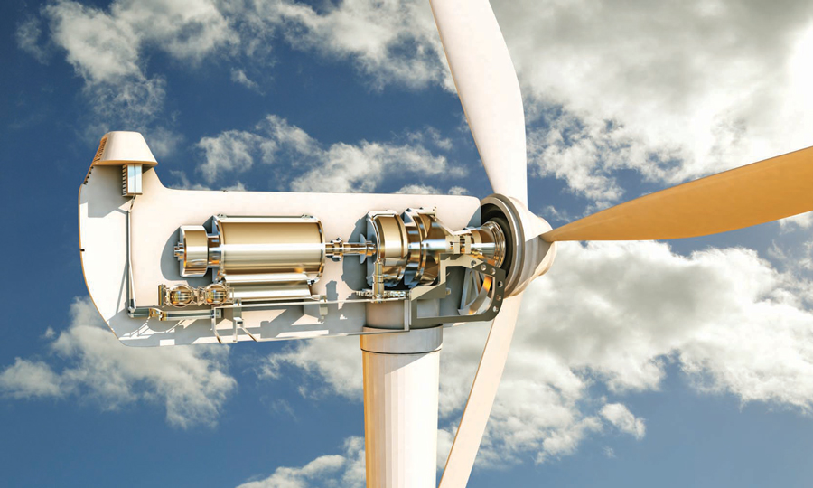
A DFIG generator (Figure 1) consists of an asynchronous generator that includes a wound rotor, a brush exciter system, and a three-phase stator. An inverter connected to the power leads of the generator stator feeds an inverter connected by slip rings to the rotor to speed up or slow the air-gap magnetic field to a constant speed to control the output frequency. The generator connects through a coupling to a three-stage gearbox with one or more planet stages. The carrier of the planet gearbox connects to the main shaft, which is normally supported by two double-roller bearings that support the hub and blades.
Common defects in a DFIG wind turbine and powertrain include:
- Generator:
- Bearings
- Collector rings
- Rotor
- Stator
- Rotor Leads
- Gearbox:
- High-speed bearings
- Mid-speed bearings
- Hollow-shaft bearings
- Planet bearings
- High, mid- and sun gears
- Planet to ring gears
- Main bearings
- Blades:
- Misalignment
- Delamination/lighting damage
Each of these can be evaluated and any related defects can be detected.
ELECTRICAL SIGNATURE ANALYSIS BASIC THEORY
ESA utilizes the magnetic field in the air gap between the rotor and stator, influenced by various defects that lead to distortions in the current and voltage waveforms. In addition to analyzing power quality, the distortions can be mathematically modeled to identify specific fault characteristics. Most of the defects are identified with similar multipliers as with vibration analysis with the exception that the signatures are amplitude modulated with line frequency as the carrier frequency. As a result, when fault frequencies are less than line frequency, they show as sidebands around line frequency; when above line frequency, they are the calculated value +/- line frequency.
Radial defects such as static and dynamic eccentricity, rotor deformation, and bearing wear introduce non-uniformities in the air gap. The air-gap flux density can be modeled as shown in Equation 1.
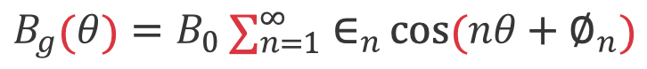
Where: is the nominal air-gap flux density; represents the magnitude of the n-th harmonic due to defects; is the angular position; and is the phase angle of the n-th harmonic.
The distorted waveform is represented as Equation 2.

Where: is the fundamental EMF and represents the n-th harmonic of the EMF.
The distorted EMF leads to a distorted current waveform such as identified in Equation 3.
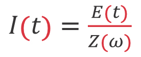
Where: is current at time increment and Z represents the impedance of the electric machine.
The torsional effects we will consider will be those that result from forces on the shaft from the driven equipment, causing periodic variations in the rotor position and affecting the air-gap length as shown in Equation 4.
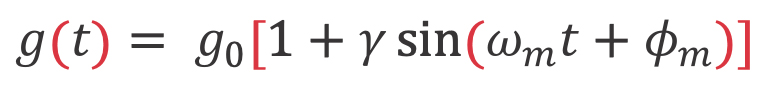
Where: is the effective air-gap magnetic field at time due to torsional defects; is the nominal air-gap length; is the amplitude of the variation due to torsional defects; is the mechanical angular frequency; and is the phase angle of the variation.
The time-varying air gap affects the magnetic linkage, impacting the magnetic field and current waveform as shown in Equation 5.

Where: is the magnetic linkage at time ; is the nominal flux linkage; and represents the n-th harmonic of the flux variation.
This also induces harmonics in the back EMF and affects the current waveform similarly to radial defects and, as a result, the same as in Equation 2. As both radial and torsional defects coexist, and their combined effects on the magnetic field, voltage, and current waveforms are more complex, the overall air-gap variation can be modeled as Equation 6 at time .

The combined magnetic field is shown in Equation 7 and the combined EMF and current waveform include harmonics from radial and torsional defects as shown in Equation 8. Both equations are the combined radial and torsional results for Equation 1 and Equation 2 at time .


The dampening effect across each of the components, including the coupling and gearbox, needs to be considered. The losses related to these components result in sound, heat, and vibration. The torque is generally well transmitted with total losses normally falling at just a few percent. In the case of rigid couplings and gearboxes, the torque is generally not considered significant enough and in worst-case conditions may result in a few dB of change.
The line frequency is considered our carrier frequency with defect signatures identified as message frequencies, much like radio signals. As shown in Equation 9, the AM signal for voltage or current can be shown with as the message (defect) signal.

Where: is the total waveform; is the amplitude of the carrier signal and is the carrier frequency.
The result in a Fast Fourier Transform (FFT) spectrum would be a prominent peak at the carrier frequency (line frequency) and sidebands of the message signal such that . The conversion to -dB for each frequency is found in Equation 10.
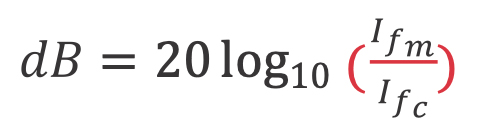
Where: the value is 20 times log 10 of the defect current divided by the carrier current and is the modulated defect frequency.
When we are above the carrier frequency, the resulting peaks show as in Equation 11 with the values in dB still calculated as shown in Equation 10.

In summary, Equation 11 describes an amplitude-modulated signal where a carrier signal with amplitude and frequency is modulated by a defect signal with amplitude and frequency . The result is a signal that contains the original carrier frequency and two additional frequency components: and . These additional components are known as sidebands and represent the effect of the defect modulations in the air gap from radial and torsional conditions on the carrier signal. The conversion of these defect sidebands will be higher frequency peaks at +/- the line frequency of a calculated fault value, sometimes with harmonics of the specific line frequency sidebands. The peaks are relatively the same values of severity regardless of load when converted to dB values.
While signatures are generated in a similar manner with vibration, ESA counts down from the peak voltage or current allowing the ability to determine a defect and severity. If demodulated, the result is the existence of a peak but not the severity.
ROTOR WYE RING DEFECTS
One of the more common and serious generator defects is the fracture of rotor wye rings. From a final detection standpoint, the current will oscillate at twice the slip frequency, called pole-pass frequency (PPF). At this point, a wind generator will usually fail within hours. The general cause of failure is either a fracture to the wye ring, which is a hoop that connects the center point of the winding to complete the connection, or the connecting tabs or leads. The challenge with this type of failure is that the damage can be repaired up-tower (Figure 2) if it is caught before the second fracture occurs, which generally causes a catastrophic failure. An up-tower rotor repair is generally a half-day and a fraction of the cost of removing and installing a replacement or spare.
As the first fracture starts, there is a change in the rotor circuit impedance. This results in an unbalanced rotor magnetic field emulating dynamic eccentricity in which the rotor magnetically orbits in the air gap. The PPF is calculated as shown in Equation 12 and dynamic eccentricity is calculated as shown in Equation 13.
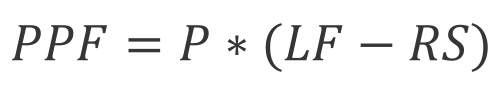
Where: is the pole pass frequency; is the line frequency; and is the running speed all in Hz.

Where: is dynamic eccentricity peaks; is the number of rotor bars/slots; is the running speed in Hz; and is the line frequency in Hz.
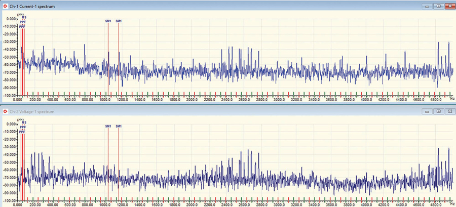
The amplitude of either the PPF or dynamic eccentricity depends on the platform but does not depend on the load (Figure 3). Another important distinction is that the location of the peaks varies with operating frequency (air-gap speed) but not load. The peaks we would be looking for on a machine operating at 1,215 RPM (20.25 Hz) and 54 rotor slots would have a PPF of 1.5 Hz (6 poles times 0.25 slip) and dynamic eccentricity frequencies of [773.25; 813.75; 892.75; 933.25; 1013.25; 1053.75; 1133.25; 1173.75; 1253.25; 1293.75; 1373.25; 1413.75] starting at cut-in through full load.
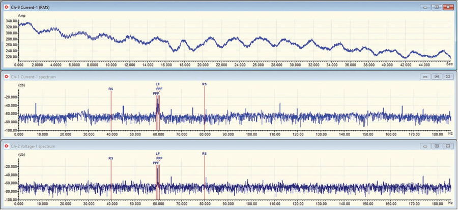
(Data Collected at 360 Hz for 39 seconds)
STATOR WEDGE LOSS
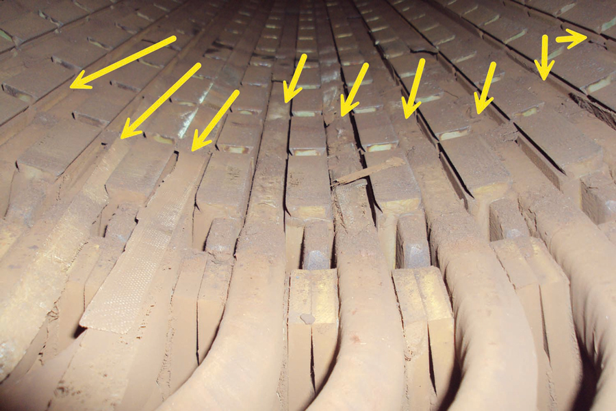
A majority of wind turbine generators use ferrous wedges to reduce air-gap harmonics, resulting in improved efficiency, reduced noise, and cooler operation. When balanced, there are no peaks. However, when wedges become loose or come out of the slots (Figure 4) due to poor keying, moisture exposure causing degradation of the ferrous materials, or coil looseness, a stator signature becomes dominant. The signature appears as in Equation 14 with any decibel level above the noise floor indicating wedge issues or coil movement.
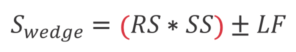
Where: is the number of stator slots.
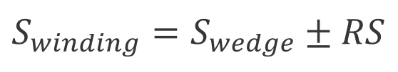
As the dB level increases above the noise floor, more wedges have been dislodged. The exception is when coil vibration, including endwinding vibration, occurs in over-extended or loose coils, in this case, increasing dB levels generate a warning prior to coil failure. These will often be found with a stator winding signature as shown in Equation 15.
A signature associated with winding stress, which can indicate insulation breakdown, sparking, or partial discharge, indicates the final stages toward winding to ground or winding short defects (Figure 4). When there is a combination of the above, action should be taken immediately, often requiring insulation repair or rewind. When caught before the winding stress signature, wedge repairs may be possible (Figure 5).
MAIN BEARING DEFECT
The main bearings are farther out on the powertrain. In most DFIGs, two main bearings will be mounted on a main shaft that also supports the hub and blades. The associated frequencies would be based on the speed of the shaft times each multiplier associated with the inner race, outer race, cage, and rollers. Most blades operate under 20 RPM with the maximum speed limited by the tip speed and potential damage when maximum speeds are exceeded. As with other data less than the line frequency, the data will show on either side of line frequency. For instance, if the outer race multiplier is 0.9661/Hz and the running speed is 19 RPM (0.317 Hz), then the value would be 60 Hz +/- 0.306 Hz or peaks at 59.694 Hz and 60.306 Hz. It is important to understand that the resolution of the ESA device is critical as there will be a large number of frequencies in this area.
An outer race signature on a main bearing often indicates poor lubrication replacement where outer race grease can dry with the signature being the result of the rollers passing over the dried grease (Figure 6).

(Data Collected at <10 kHz)
TRENDING
For most defects in wind turbines, quarterly testing over time would allow for the detection of new conditions and some level of trending. To make the most out of the technology, continuous monitoring is available for earlier detection of defects and to provide information to optimize operations. One of the ESA’s strengths is that the peaks remain constant, or vary only by one or two dB, providing an excellent ability to trend any defect signatures.
CONCLUSION
Electrical signature analysis is an extremely powerful tool for detecting electrical and mechanical conditions throughout the entire generator and powertrain of wind turbines. The more successful applications require a high resolution of at least 0.005 Hz (bin size) near line frequency and 0.01 Hz in frequencies over 180 Hz. This provides the ability to detect the most severe conditions such as wye ring fractures, stator wedges, gears, and bearings including planetary bearings and the main bearings. Additional conditions are also detectible and trendable, regardless of generator loading.
REFERENCES
- American Clean Power Association. Accessed at www.cleanpower.org.
- H. W. Penrose. “Evaluation of Asynchronous Wind Generator Stator Magnetic Slot Wedge and Coil Movement Using Electrical Signature Analysis,” 2021 IEEE Electrical Insulation Conference (EIC), Denver, CO, USA, 2021, pp. 1-4, doi: 10.1109/EIC49891.2021.9612312.
- K. Alewine and H. Penrose. “Field Experiences Utilizing Electrical Signature Analysis to Detect Winding and Mechanical Problems in Wind Turbine Generators,” 2020 IEEE Electrical Insulation Conference (EIC), Knoxville, TN, USA, 2020, pp. 246-248, doi: 10.1109/EIC47619.2020.9158573.
- H. W. Penrose. “Evaluation of Stator and Rotor Interturn Stress with Electrical Signature Analysis in Variable Frequency Drive and Wind Generator Applications,” 2020 IEEE Electrical Insulation Conference (EIC), Knoxville, TN, USA, 2020, pp. 274-277, doi: 10.1109/EIC47619.2020.9158738.

Howard W. Penrose, PhD, CMRP, CEM® CMVP is President of MotorDoc® LLC, a veteran-owned small business. He was a U.S. Navy electric machine repair/rewind journeyman (NEC 4619/4621) and is the 2022-2025 Chair of Standards Development at American Clean Power. Penrose is the past chair of the Society for Maintenance & Reliability Professionals (SMRP); past chair of Chicago Section IEEE; an active member of IEEE standards committee(s); past Senior Research Engineer at the University of Chicago Energy Resources Center; chair of the committee for wind/solar/energy storage standards for the USA through American Clean Power (formerly AWEA); and the U.S. appointee to CIGRE Working Group A1 Electrical Machines for those topics. He is a five-time recipient of the UAW-GM People Make Quality Happen Award; a leading researcher of ESA/MCSA applications; and has worked with diverse design teams including the GM hybrid Tahoe and Volt, John Deere 644 and 944 hybrid construction tractors, LVAD heart pump, flywheel generators, and high temperature/low atmosphere electric machines. He serves on the SMRP government affairs team for workforce, smart grid, cybersecurity, and infrastructure, among numerous other energy/environment/ workforce programs. Penrose received his PhD in industrial-general engineering and is certified in data science and machine learning from Kennedy Western University, Stanford University, the University of Michigan, IBM, and AWS. He is also a Certified Maintenance and Reliability Professional through the Society for Maintenance and Reliability Professionals, and a Certified Energy Manager and Certified Measurement and Verification Professional through the Association of Energy Engineers.