

Solar farms are especially at risk because they are exposed to the elements and require dedicated electrical maintenance. Good grounding is essential, as the panel produces high DC voltages that can be sources of shock, fire, induced voltages, and electromagnetic interference on lines. Solar arrays sometimes use Class II modules, DC cables, and connectors. An isolation transformer connects these to the line (mains) through an inverter.
There are two types of grounding configurations for photovoltaic (PV) systems: floating and grounded or earthed. In a floating system, non-current-carrying conductive parts such as metal frames and things that could become energized in a fault situation but are not part of the electrical system, are connected to the ground to prevent dangerous or destructive voltages from developing. This configuration leaves the array frame floating. Faulty equipment or damaged insulation can produce accidental ground leakage. Such systems require specially listed inverters with array fault detection capability, wiring protection, overcurrent protection, disconnecting devices, and ground-fault protection in both DC conductors.
By contrast, grounded (earthed) systems connect a current-carrying conductor in the electrical system to ground potential. A bonding to earth is completed by connecting to any live DC conductors. Planned ground leakage occurs as a consequence of the design of the array.
PV systems, by default, should be equipment-earthed and, in most cases, protected with a system ground. In such systems, a ground-fault condition is detected by the current flow in the grounded conductor and electrode. This triggers the circuit’s disconnection, and the inverter displays a ground-fault alarm. The connection between the grounded conductor and the grounding electrode is usually made through the ground-fault protection device. Lightning strikes are common causes of damage to solar arrays. There may be a direct hit; however, a nearby strike may also induce surges in the array conductors and the AC cables.
It is apparent that PV systems must be regularly tested and maintained against these potential problems of stray ground currents to remain safe and fully operative. Record keeping is invaluable from the time of initial commissioning and subsequently upon changes and modifications. Being able to compare system changes to stored records enables the maintenance staff to recognize potential or developing problems and head off developing issues before they become inordinately costly or dangerous. Such a thorough and conscientious program typically consists of eight steps:
Visual Inspection
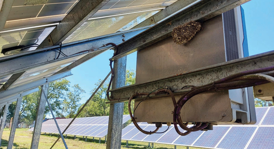
What may seem like a no-brainer is a valuable and often time-efficient means of adequate maintenance. Look for incomplete installation details and sufficient compliance with local applicable standards. These shortcomings can be inordinately costly if left unattended until well into the life span of the array. Visual inspection can spot physical damage and equipment modification or degradation from environmental conditions such as temperature extremes, dust, corrosion, and moisture. Solar arrays may also be subject to considerable damage from rodents chewing wires and birds building nests in the structure.
Continuity
This testing verifies that adequate low-resistance bonding has been established between module frames, conductors, structures, connectors, and other terminations in de-energized circuits and the grounding system. Simply bolting or crimping metallic components together is insufficient to guarantee that the required current flow can be accommodated without overheating, sparking, or other dangers, not to mention the possibility that in the complexity of a large grid, some connections and terminations may be missed altogether. The grounding electrode conductor should be verified as continuous, and accepted methods should assure the viability of irreversible splices, welds, and other connections.
The connection of the grounding conductor to the ground electrode (ground rod) must also be verified, as it may be called upon in fault situations to accommodate currents well above system values. It also includes continuity bond testing of metal cable trays, enclosures, frames, fittings, and other components that may be grounding conductors in fault situations. Electrical continuity can be lost due to inadequate mechanical installation. Be sure to test the electrical continuity between the grounded PV array source circuit, output circuit conductors, and ground electrode conductors. Remember to re-establish this bonding when equipment is removed for service or replacement.
Polarity
Correct polarity should be verified for PV DC circuits, and correct termination should be used for DC circuit equipment. This is accomplished by measuring the voltage on energized circuits before closing disconnects and operating the system. The points in the system where this test should be implemented are PV modules, PV source and output circuits, disconnect means, battery and charge controller circuits, inverter input terminals, and electrical loads. Every source circuit and PV power source should be tested before connecting to any DC equipment. Accidentally reversing the polarity of an array connection to a battery is a severe potential danger leading to accidents, equipment destruction, and even loss of lives.

Voltage and Current
Confirm that the array and system operate according to expected commissioning and equipment manufacturer’s specifications. The amount of voltage and current produced from the array should meet the design specifications for the irradiance and temperature level at the testing time. The design specifications will provide expected output curves for the temperature and solar irradiance range of operation. The voltage and current must also be measured in DC and AC before closing disconnects and starting operation. AC voltage and phasing are verified at the utility supply, inverter AC terminals, and disconnects. Maintenance professionals should check the DC voltage and polarity for the PV array source and output circuits, as well as DC disconnects. DC voltages and polarities on batteries, battery chargers, and controllers should also be checked.
Open-Circuit Voltage
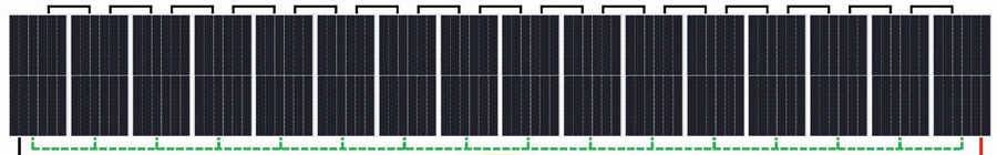
This is performed to prove the polarity of the array sourceand document the string voltages. Suitable testers must be capable of withstanding voltages over 600 V AC, and DC. Differences in voltage values within 5% are typical between strings within an array. Low-voltage output may be due to damage and installation errors such as inappropriate array cabling, damaged modules, or damaged bypass diodes. These values can also be affected by temperature and irradiation during testing, with changes in the range of 2.5% per 10°C.
To identify faulty strings, first verify the open voltage of all strings. Then divide the voltage of a good string by the number of modules in series. This determines the module voltage. For example, if the voltage of a string of 10 modules in series is 500 V, then the voltage of each module is 500 ÷ 10 = 50 Vdc per module. If measuring on a faulted string, the voltage equals 400 V, and the voltage per module is 50 V, then 400 ÷ 50 = 8.
To detect ground faults in a grounded string of solar PV panels, you can use a high-quality voltmeter. For instance, if you have 16 panels and each panel has an open-circuit voltage (Voc) of 50V, then the total string voltage would be 800V. When there is a ground fault, there will be a voltage imbalance in the circuit. This imbalance can be measured between the positive terminal and ground, and then between the negative terminal and ground. If the positive-to-ground voltage is 200V and the negative-to-ground voltage is 600V, then the ground fault is between panels 4 and 5 from the positive side. You can identify this by taking the voltage to ground value and dividing it by the Voc of the installed panels.

Short-Circuit Current
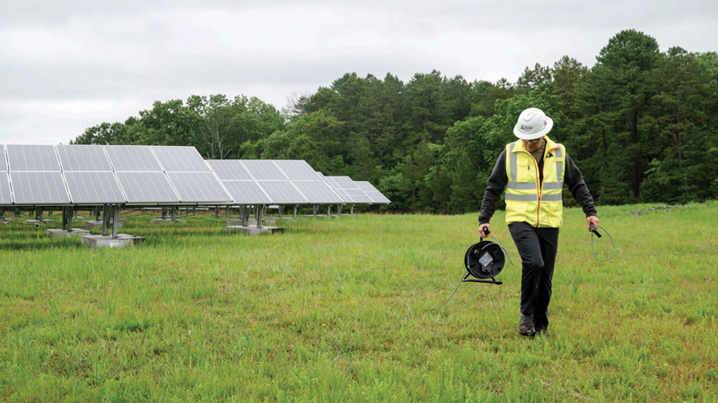
This test (Isc) requires using a tester capable of withstanding DC currents higher than 10 A as well as suitable shorting devices to perform the test safely. The short-circuit current of a PV array is proportional to the solar irradiance on the system. This test should be performed briefly under clear skies with the PV modules free of dust or shade. Acceptable differences should fall within 5% between each PV string.
Insulation Resistance
Insulation degradation is a common cause of electrical failure anywhere and everywhere in the electrical grid. Solar fields are no exception. Testing must be done within PV arrays and system circuits. Such testing is performed by applying a DC voltage, typically anywhere from 50 V to 5 kV, depending on the point in the system, between conductors, or from conductor to ground. This is always done while de-energized. The instrument used to perform the test — an insulation tester — applies an operator-selected test voltage across the insulation under test and measures the amount of leakage current through the insulation. The insulation stands between the two poles of the applied voltage, and any current flow indicates the insulation’s condition. Knowing both test voltage and resultant current, the tester then calculates and displays, by Ohm’s Law, the resistance of the insulation under test.
Healthy insulation would pass only pico amps of leakage current, below the measurement sensitivity of all but the most sophisticated testers, and hence would display the test result as the well-known “Infinity” reading, which is always acceptable. However, as insulation deteriorates, this current — called leakage — rises and becomes measurable, typically in Megohms. By the time it reaches 5 mA, the human shock level is high, and the equipment is deteriorating and needs repair or replacement. This is generally around 1 Megohm or higher for systems with operating voltages of 120 V and above.
For systems operating at voltages lower than 120 V, 0.5 Megohms and above are acceptable. Environmental conditions, sun, moisture, gnawing animals and insects, mechanical impacts, and regular operation all wear down the quality of insulating materials. Bonding connections are left in place while surge suppression is removed from the circuits. Ensure reliable electrical and mechanical contact between test leads and circuits under test. Some connections may require grinding or filing. Discharging stored capacitance at the end of the test is of great importance. Enough energy can be stored to be lethal. Fortunately, all good-quality modern testers perform this potentially life-saving function automatically.

Such testing can be performed between positive DC conductors and ground, negative DC conductors to ground, or between the shorted positive and negative conductors to ground, by the operator’s judicious connection of test leads. Suitable shorting devices are needed to perform the test safely. In floating systems, where modules and structures are not provided with metallic frames with a bonded connection to the earth, this test should be performed between array cables and ground and between array cables and frame.
Earth Leakage Current
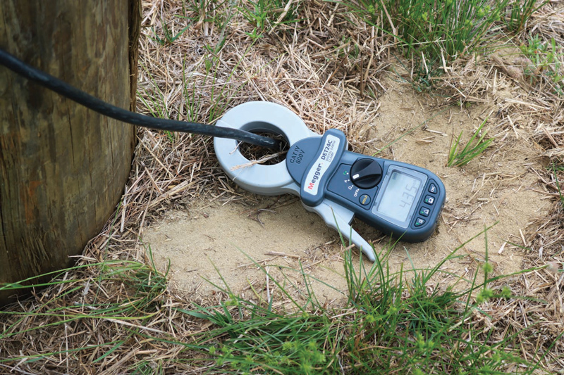
Systems equipped with residual-current devices (RCDs) can be tested for nuisance tripping. Such devices monitor the current flowing in line conductors and compare it to the return current in the neutral. If the difference in currents exceeds the device’s sensitivity setting (typically in milli-amperes), the device will trip and open the circuit. A clamp-on ammeter is clamped around the line, and neutral conductors are clamped separately. The difference between the two readings is the earth leakage current.
CONCLUSION
The enormity and complexity of solar fields make them a unique challenge to maintain. Although they may appear static electrically, they are just as dynamic as visibly operating equipment such as a rotating generator. A dedicated electrical testing and maintenance regime is required to ensure reliable operation and avoid costly outages. Using test equipment that includes data storage and downloading capabilities can increase the efficiency of maintenance and testing programs. Analyzing and maintaining a well-organized electronic file of test data can turn a potentially chaotic situation into an effective maintenance and prevention model.

Ahmed El-Rasheed, PhD, is the Renewables Industry Director at Megger, with over 15 years of experience in electrical engineering. His area of expertise is electrical measurement, and he has been a regular contributor at industry conferences and publications with notable papers on insulation testing, ground testing, and multi-sensor integration using artificial intelligence. He sits on several international standards committees, including at IEC, BSi, SCC, and IEEE. He gained his PhD in electrical and electronic engineering from the University of Liverpool, UK.