Locating faults in buried or concealed cable is one of the most demanding, inventive, and interesting chores in all of electrical maintenance. The operator’s skills, knowledge, and ingenuity are paramount. When the power goes out, an entire facility, neighborhood, or community can be abruptly shut down without warning. Normally, this goes largely unnoticed as the utility seamlessly switches to another feed. But there are situations where power can be out for extended periods and constitute a major problem. Either way, the fault must be located and repaired, often under time pressure.
At one time, operator skill was the defining feature of this operation. Veteran repair techs could walk the line and feel the vibrations from the arc with their feet. At other times, it could be heard. Obviously, these WERE not scientifically reliable methods. They depended on operator skill and experience, and that was not always available or effective. Acoustic and electromagnetic pickups were invented to detect a thump and trace the path of the buried cable more accurately and reliably.
NEW TECHNOLOGY
Rescuing the cable and getting the line restored is accomplished using a number of instruments and techniques. These include time domain reflectometer (TDR), arc reflection, and thumper. Fundamentally, a capacitor builds up a considerable charge and discharges it down the line between conductors. These can be phases, ground, shield, sheath, jacket…as long as the two conductors are metallic and parallel and separated by a constant thickness of insulation. The pulse is affected when it encounters the fault. Some energy is reflected back and can be detected, such as by using a TDR, or it may arc and be detectable from the surface. Several methods and technologies have evolved to make use of these parameters, and these applications are improving all the time.
Stand-alone TDRs can be handheld, battery powered, and completely safe. They can be all that is needed for wiring like telecommunications twisted pair and concentric. But for power cable, a TDR alone may miss all but the most profound faults, such as bolted faults or complete opens. For the far more common problems, a thumper or thumper-TDR combination (arc reflection) are in order. In these operations, grounding is absolutely essential.
GROUNDING
In all of these functions, grounding is an important element that is subject to being overlooked in the rush to find the fault and re-energize the line. Lack of proper grounding can make the test ineffective or more difficult to interpret. Worse, it can produce significant damage to fault locating equipment and even imperil worker safety.
In many common electrical operations, grounding is regarded as merely an extraneous level of protection that can be overlooked or forgotten without pronounced consequences. But in thumping, a prodigious amount of energy is applied to a faulted circuit that no longer conforms to design parameters because it has broken down in some undefined manner. Grounding is therefore an indispensable part of the testing procedure.
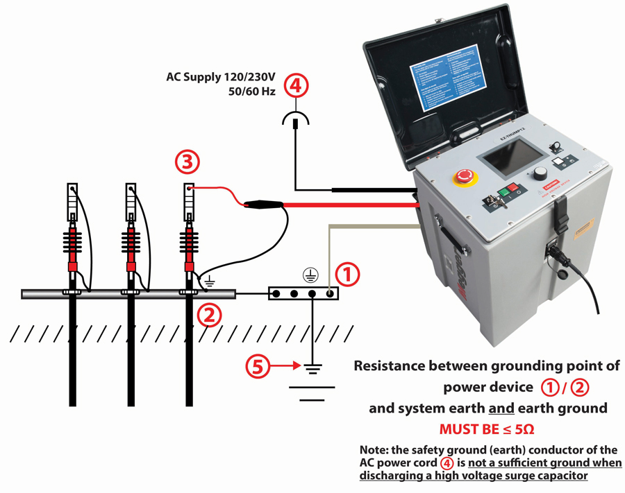
The tester should have a permanently attached safety ground lead that is connected to the system grounding point of the power device (transformer, switchgear, etc.). This should be attached by a firm clamp, not an alligator clip, because the levels of energy delivered by a thumper can knock an alligator clip loose and leave the system dangerously floating.
Temporarily driven ground rods are also discouraged because these may have too high a resistance to remote earth and therefore are not sufficiently protective. In the worst case, a large pulse can even dislodge them from the earth. The high-voltage return or shield of the test lead is connected (again via clamp, not clip) to the shield or neutral of the test item, and this is also bonded to the system grounding point. This grounding point in turn must have a resistance of no more than 5 Ω to remote earth measured with a dedicated earth ground meter.
Herein lies an imminent danger. This safety grounding must not be cavalierly regarded and ignored. If it cannot be achieved, then applicable safety procedures for hot, live, or energized work sites must be followed because the entire test circuit is floating above ground, presenting a serious hazard.
Safety Ground
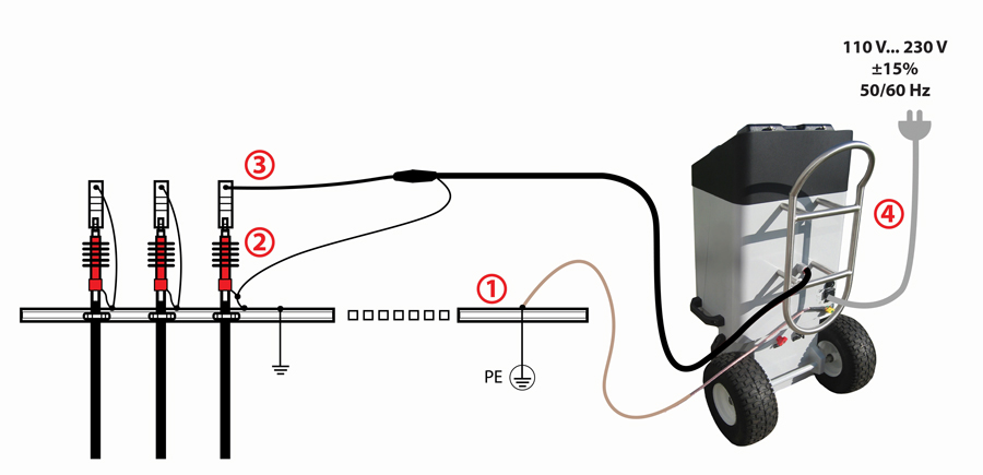
Performance and safety are inseparable in fault locating. The surge generator may output energy up to 10 kilo-joules at as much as 30 kV, so safe discharge is paramount for operator safety. Additionally, neither capacitor nor cable can be left in a charged state. The surge generator’s safety ground is connected to the system grounding point. The cable under test can be connected in a single-point grounding scheme (Figure1) or separately grounded and paralleled to the system ground (Figure 2). The latter configuration is preferable but used less often because of time and convenience.


At the start of a test, check the isolated cable for stored voltage and ground it. The surge generator’s safety ground is connected to a system grounding point at the transformer, switch cabinet, or pole. Next, the high-voltage return lead is connected to a shield or neutral as close as possible to the high-voltage connection. The neutral is grounded at both ends. Finally, the high-voltage test lead is connected to the phase conductor.
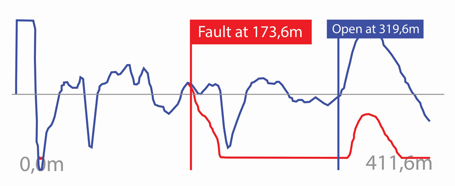
At the conclusion of a test, a mode switch is moved to ground, and all stored energy is discharged. Disconnection of leads is made in the opposite sequence. The safest and lowest-resistance safety ground connection is system neutral, which will keep the system at zero volts in case of a back feed. If all is done correctly, a readable trace will appear on the test instrument’s display, indicating the distance to the fault (Figure3).

Bonded Grounds
Another interesting and ingenious use of grounding in fault location occurs with bonded grounds in conduit such as might be found with single-phase PILC cable. When there are well-bonded grounds at every manhole, impulse current through the phase conductor is slightly greater than return current in the neutral. This is because a small amount of return current flows through the neutral beyond the fault and into the earth through the bonded ground at the next manhole. This current returns to the surge generator through the bonded grounds before the fault. When relative readings are taken with a sheath coil pickup before and after the fault, the readings will all be positive. However, those taken before the fault will be higher in magnitude than those taken after the fault. Readings taken on the bonded ground at the second and succeeding manholes after the fault will be zero.
TRACING THE CABLE
Once the distance to the fault has been established, the job has only begun. In which direction is it? Accurate wire maps are a luxury. In most cases, the cable route must be traced. This can be done with specialized route tracers that place a trace signal on the cable. But there are many potential variables, and picking up the signal can be difficult. Various types of instrumentation and techniques exist, and grounding can assist in providing a strong, traceable signal.
If possible, drive temporary ground rods at the transmitter and at the opposite end of the cable. Soil is a relatively good conductor because of the moisture and dissolved salts it contains and also because there is so much of it that current can find a relatively low-resistance path. Connect one lead from the transmitter to the faulted conductor and the other to the nearby ground rod. Pouring water on the rod and/or using a longer rod helps increase current flow and establishes a more detectable signal. The ground rod is placed off to the side, being careful to avoid other cables and pipes. Vary the position of the rod to provide the strongest signal. This configuration is strong because it is comprised of direct current flow and capacitive coupling. If the other end of the cable is not accessible, just the nearby ground may be enough to provide a detectable signal through capacitive coupling, but this is a weaker arrangement and may be harder for the pickup to detect.
CONCLUSION
Being cavalier about grounding must be scrupulously avoided in cable fault location. Here, proper grounding is integral and indispensable not only to the expressed purpose of finding the fault, but also — and more important — to keeping equipment safe from damage and protecting personnel from injury.
Once again, modern technology alleviates a serious problem with a reliable and ready solution. A dedicated transformer applies a small AC current between the surge return and the safety ground and checks the resistance. If grounding is not thoroughly established, the operator is alerted, and the operation is disabled until safely corrected. From walking the line in the early days, cable fault location has relentlessly improved to the thoroughly safe and reliable operation afforded by modern technology.

Jeffrey R. Jowett is a Senior Applications Engineer for Megger in Valley Forge, Pennsylvania, serving the manufacturing lines of Biddle, Megger, and Multi-Amp for electrical test and measurement instrumentation. He holds a BS in biology and chemistry from Ursinus College. He was employed for 22 years with James G. Biddle Co., which became Biddle Instruments and is now Megger.
