

Multi-function numerical generator protection relays can calculate the insulation resistance of a synchronous generator field winding to ground. The calculation can be performed on an energized or de-energized generator. The particular relay discussed in this article uses a separate module located close to the rotor slip rings and brushes to monitor the field. The close proximity of the module to the rotor slip rings and brushes minimizes transient voltage induced on the metallic connections (see the connection diagram in Figure 2). The measurement module transmits the insulation resistance value to a generator relay via a fiber optic link. The relay compares the calculated insulation resistance with pickup settings to either alarm or trip.
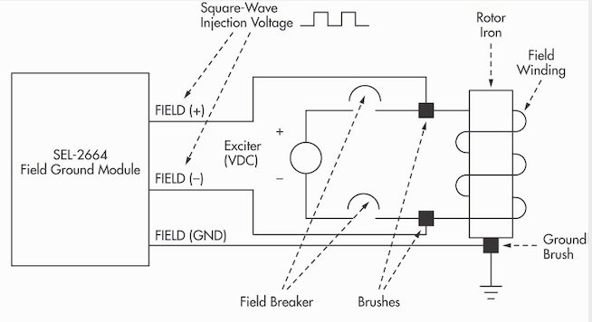
Figure 2: Diagram of Connections
The relay uses the calculated insulation resistance value to detect a ground fault in an ungrounded field winding of the protected generator. This allows the generator owner to avoid any significant damage to the generator by taking corrective actions before a second ground path occurs.
The measuring module (Figure 1) works with continuous field voltages as high as 750 Vdc and can withstand up to 1500 Vdc for 1 minute.
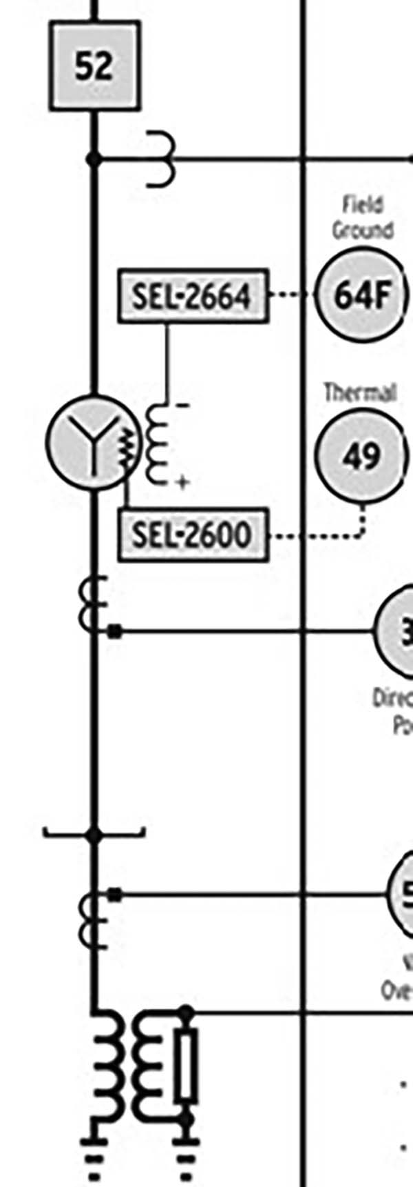
Figure 1: Single-Line Diagram of Measuring Module
A generator field is an ungrounded single-circuit winding that is wound on the rotor. A DC source is connected to the field winding to produce the required magnetic field. This exciter DC voltage source typically ranges from 48 V to 825 V.
Insulation deterioration or breakdown can cause the field winding to contact the rotor iron. This first ground will not generally affect the operation of the generator. A second ground will cause a portion of the field winding to be shorted, resulting in unbalanced air-gap fluxes in the generator. This in turn can cause rotor vibration that can damage the generator. It is best to detect the first ground and take corrective action by programming the relay to alarm or trip following detection of a field ground.
Data Packet
The measurement module transmits a data packet to the relay that contains the insulation resistance and self-test status. Measurements are transmitted as fast as every half second. No settings are required for the module. The fiberoptic port in the module has a built-in fiberoptic transceiver transmit circuit. The relay has a fiberoptic serial port to directly connect to the measurement module.
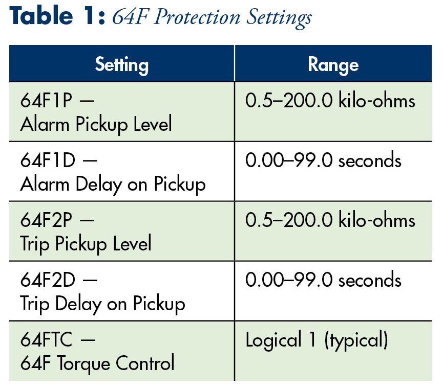
Alarm and Trip
The relay has two independent pickup levels to compare versus the calculated insulation resistance. Program the field ground protection elements to output contacts to alarm or trip. The field ground protection function covers a range of 0.5 to 200.0 kilo-ohms (Figure 3).
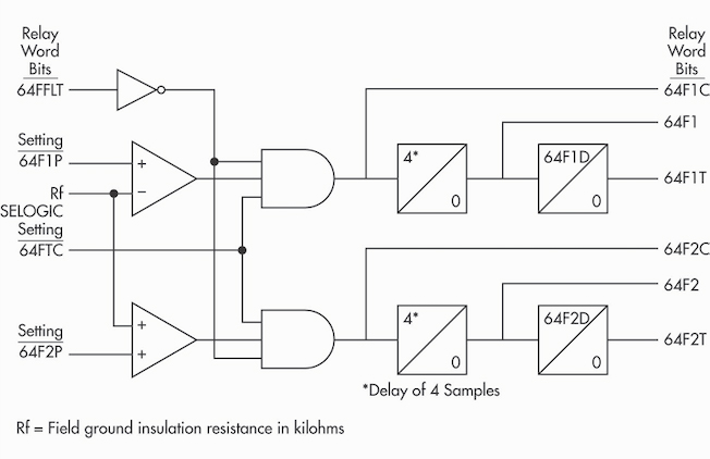
Figure 3: Alarm (64F1) and Trip (64F2) Logic
If relay word bit 64FFLT equals logical one, this indicates a non-functional measuring module or severed fiberoptic connection. The 64F elements are not calculated; 64F1, 64F1T, 64F2, and 64F2T relay word bits are set to zero; and all accumulated timer values are reset to zero.
Test Guidelines
To verify proper connection via fiberoptic link (Figure 4):
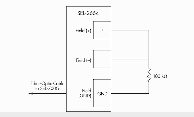
Figure 4: Test Connections
- Step 1. Disconnect the field winding from the measuring module.
- Step 2. Connect the measuring module to the relay and enable 64F protection.
- Step 3. Record the value of Rf using the METER command for the relay. It should read 20,000 kilo-ohms.
- Step 4. Connect a resistor decade box between the field (+) and field (GND) terminals.
- Step 5. Short the field (+) and field (–) terminals.
- Step 6. Select the resistor value to be 100k ohms on the resistor decade box.
- Step 7. Wait 30 seconds and record the value of Rf using the METER command for the relay. Make sure the reported Rf value is within the stated accuracy limits.
Data Recorder
The relay can periodically record the analog quantities it measures such as voltage and current. The relay stores these values in non-volatile memory. Use this function to track the value of field insulation resistance over time. The relay for this example is programmed to record the phase current on both sides of the stator winding, phase-to-phase voltage magnitude at the generator bus, neutral voltage magnitude, rotor field ground resistance, volts per Hertz, and frequency with respect to the generator bus every 10 minutes (Figure 5).
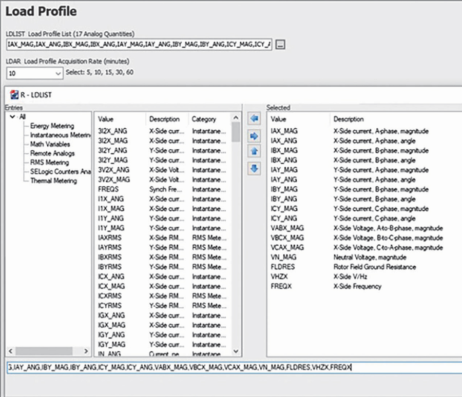
Figure 5: Data Recorder Configuration
Conclusion
Implementing a multi-function numerical generator protection relay can calculate the insulation resistance of a synchronous generator field winding to ground and record the value over time. The relay uses the calculated insulation resistance value to detect a ground fault in an ungrounded field winding of the protected generator. This allows the generator owner to avoid significant damage to the generator by taking corrective actions before a second ground path occurs.
 Steve Turner is in charge of system protection for the Fossil Generation Department at Arizona Public Service Company in Phoenix. After working with Beckwith Electric Company, Inc. for 10 years, Steve spent two years as a consultant in San Diego. His previous experience includes positions as an Application Engineer at GEC Alstom and in the international market for SEL focusing on transmission line protection applications. Steve also worked for Duke Energy (formerly Progress Energy), where he developed the first patent for double-ended fault location on overhead high-voltage transmission lines and was in charge of all maintenance standards in the transmission department for protective relaying. Steve has BSEE and MSEE degrees from Virginia Tech University. He has presented at numerous conferences including Georgia Tech Protective Relay Conference, Western Protective Relay Conference, ECNE, and Doble User Groups, as well as various international conferences. Steve is a senior member of IEEE and a member of the IEEE PSRC.