Distance protection measures loop impedances to determine the location of a fault on the protected line. There are six loops: A-B, B-C, C-A, A-G, B-G, and C-G. This article demonstrates how distance protection measures the apparent loop impedance for B-Phase-to-C-Phase and A-Phase-to-Ground faults. The loop impedances for phase-to-phase and phase-to-ground faults are not equivalent due to the presence of neutral impedance when ground is involved.
Proper selection of the reach settings and tripping times for the various zones of distance protection enables proper coordination between relays. Basic distance protection typically provides instantaneous Zone 1 and one or more time-delayed zones. Zone 1 can trip instantaneously since it underreaches the remote line terminal, while the overreaching zones are delayed, preventing unwanted tripping during out-of-section faults.
Phase Impedance Measurement for Phase-to-Phase Fault
Figure 1 shows the three-phase impedance diagram for a B-Phase-to-C-Phase fault on an unloaded radial overhead transmission line.

The following conditions hold true for this fault:
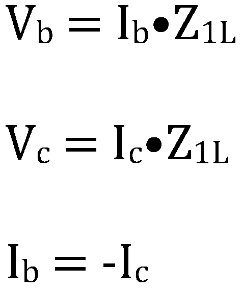
Where:
Vc is collector voltage relative to ground.
Calculate the phase loop impedance as follows:
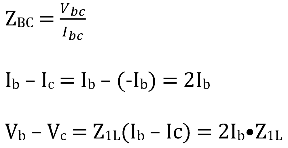
Therefore:

You can see that the relay measures the positive-sequence impedance (Z1L) of the transmission line up to the point of the phase-to-phase fault.
Ground Impedance Measurement for Phase-to-Ground Fault
Figure 2 shows the three-phase impedance diagram for an A-phase-to-ground fault on an unloaded radial overhead transmission line.

The uncompensated ground loop impedance is calculated as follows:
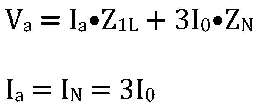
Therefore:
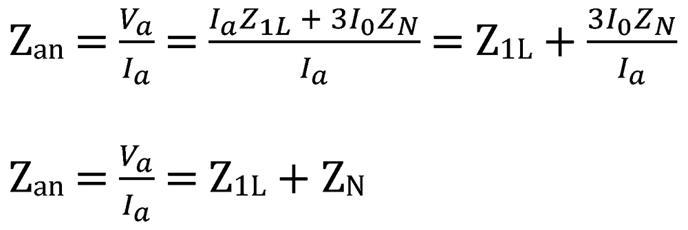
You can see that the relay measures the sum of the positive-sequence impedance (Z1L) plus the neutral impedance (ZN) of the transmission line up to the point of the phase-to-ground fault. The uncompensated ground loop impedance is greater in magnitude than the phase loop impedance. Therefore, distance relays compensate the measured fault current (Ia’), so the compensated ground loop impedance is equal to the phase loop impedance. This allows the same reach settings for each zone of phase and ground distance protection, as illustrated in Figure 3.

The following conditions hold true for this ground fault:
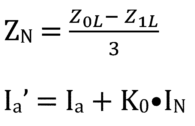
Calculate the compensation factor (K0) as follows:
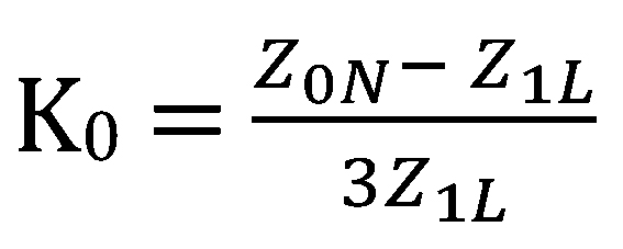
Calculate compensated ground loop impedance (Zan’)as follows:

The compensated ground loop measures the same impedance as the phase loop.
Ground Impedance Measurement for Phase-to-Ground Fault
It has been demonstrated how distance protection measures phase and ground loop impedance for phase-to-phase and phase-to-ground faults, such that both types of elements measure the same impedance up to the point of the fault. It is important to note these loop impedance equations measure the apparent impedance.

Steve Turner is a Consultant at Sargent & Lundy. He was previously in charge of system protection for the Fossil Generation Department at Arizona Public Service Company for five years. Turner formerly held positions at Beckwith Electric Company, GEC Alstom, SEL, and Duke Energy, where he developed the first patent for double-ended fault location on overhead high-voltage transmission lines and was in charge of maintenance standards in the transmission department for protective relaying. He has BSEE and MSEE degrees from Virginia Tech University. Turner is an IEEE Senior Member and a member of the IEEE PSRC and has presented at numerous conferences.
