

This article demonstrates how to use numerical generator protection relay profile capability to measure the stator ground capacitance of a large combustion turbine generator. The measurements are taken when the generator is on-line and running at full speed while the generator breaker is open (no load), and again during startup as the exported power increases.
The stator capacitance-to-ground (Figure 1) is indicative of conductive moisture and dirt in and around the stator insulation system. The apparent conductive surface area of winding insulation grows as contaminants build up. The value of the variable plate can be measured and trended over time as the change in stator capacitance-to-ground (Cg).
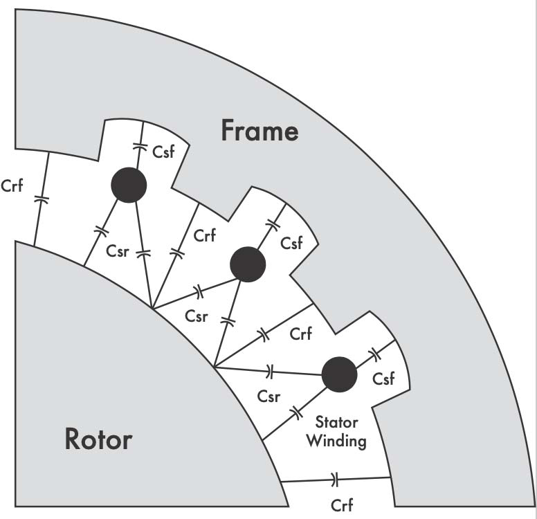
Figure 1: Stator Winding Capacitance-to-Ground
Compare the initial (baseline) measurement to future recorded values. A significant rise in magnitude may indicate one of the following conditions:
- Internal contamination
- Moisture infiltration
- Problem with the circuit cables connected to the machine
THIRD HARMONIC VOLTAGE
Generators produce varying amounts of third harmonic voltage in addition to the fundamental. The stator winding pitch — the distance between the two sides of each loop relative to the distance between the rotor poles — influences the amount of third harmonic voltage produced. The amount of third harmonic voltage generated by the machine also varies with loading. Changes in both real and reactive power alter the amount of third harmonic voltage produced.
Figure 2 illustrates the third harmonic circuit for a large unit connected generator that is high-impedance grounded. The generator step-up (GSU) transformer low-side delta winding provides third harmonic isolation from the transmission system. Note that it is assumed the low-side generator breaker is open and the machine is running at full speed (that is, no load) for the purpose of the calculations.
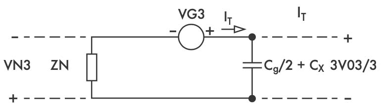
Figure 2: Stator Winding Capacitance-to-Ground
The distributed Cg is represented as an equivalent pi-section divided between the system and neutral sides of the stator windings. The system side has additional external capacitance (Cx) from the surge capacitor, isophase bus, and auxiliary transformer. Note that only the capacitance of the surge capacitor is considered on the system side for the following calculations since it is assumed that the low-side generator breaker is open. The neutral resistor (RN) is reflected to the primary.
3V03 and VN3 are measured by the generator relay, while VG3 is calculated using those two values. Note that the terms 3V03 and 3V0Z3 are used interchangeably.
VG3 ≡ Total third harmonic voltage (source)
3V03 ≡ Third harmonic voltage drop across terminal capacitance
VN3 ≡ Third harmonic voltage drop across ZN
Third Harmonic Voltage Profile
Figure 3 shows the third harmonic voltage profile captured by the generator protection relay during startup.
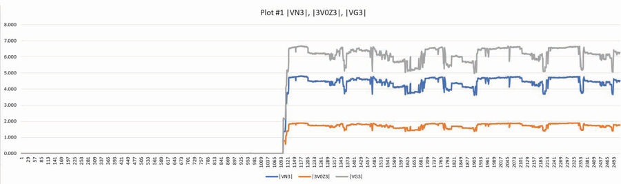
Figure 3: Third Harmonic Voltage Profile Captured During Startup
Table 1 shows the third harmonic voltage profile captured by the generator protection relay during a startup.
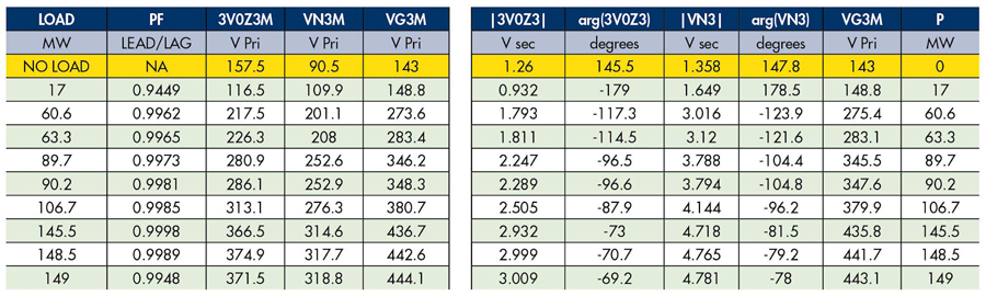
Table 1: Third Harmonic Voltage Profile
CALCULATIONS
Figure 4 represents the total third harmonic current flow through the neutral impedance ZN, which is the parallel combination of the neutral resistor RN and stator capacitance-to-ground (Cg/2). IT is the total current while IR is the resistive component and IC is the capacitive component.
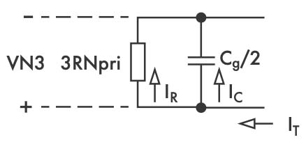
Figure 4: Third Harmonic Neutral Circuit
First, calculate the circuit impedance to solve for Cg:
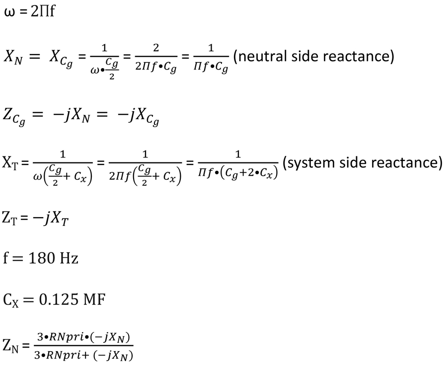
Next, calculate the third harmonic neutral voltage VN3 dropped across the neutral grounding resistor (NGR) and stator capacitance-to-ground:
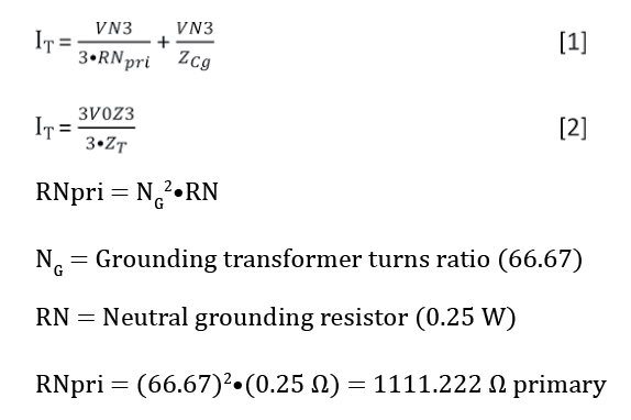
Set equations [1] and [2] equal and solve for ZCg.
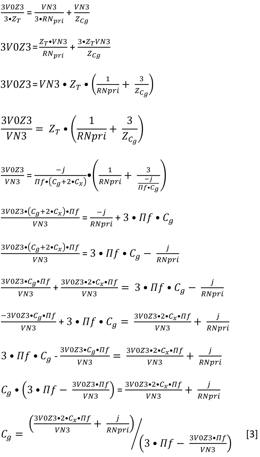
Equation [3] solves for Cg, the stator capacitance-to-ground.
CONCLUSION
This article demonstrates how to use a numerical generator protection relay profile capability to measure the stator ground capacitance of a large combustion turbine generator. Increases in the measurement over time are indicative of contamination buildup that provide guidance on when maintenance should be performed.
 Steve Turner is in charge of system protection for the Fossil Generation Department at Arizona Public Service Company in Phoenix. Steve worked as a consultant for two years, and held positions at Beckwith Electric Company, GEC Alstom, SEL, and Duke Energy, where he developed the first patent for double-ended fault location on overhead high-voltage transmission lines and was in charge of maintenance standards in the transmission department for protective relaying. Steve has BSEE and MSEE degrees from Virginia Tech University. Steve is an IEEE Senior Member and a member of the IEEE PSRC, and has presented at numerous conferences.