

Low-voltage protection is undergoing rapid evolution. For decades, microprocessor-based protective relays have been the gold standard for medium- and high-voltage power systems, offering highly configurable protection, metering, and communication capabilities. Meanwhile, circuit breaker trip unit technology remained relatively static for many years, remaining confined to the breaker frame and focused primarily on basic overcurrent functions.
This is no longer the case. The latest generations of trip units have evolved into powerful, intelligent devices with capabilities rivaling — and in some cases, matching — dedicated protective relays. They combine advanced protection, power quality monitoring, event logging, and digital communication, transforming the once stand-alone breaker accessory into an integral component of modern electrical protection schemes.
This convergence brings opportunities and challenges. Engineers, technicians, and facility owners must now treat trip units with the same design, testing, and maintenance rigor as they do with protective relays because, in many cases, a trip unit is indeed a relay by another name.
TRIP UNIT VS. PROTECTIVE RELAY ARCHITECTURE
Trip unit architecture first evolved beyond thermal magnetic overcurrent protection to systems consisting of current sensors, adjustable dial settings, and the introduction of additional features such as short-time and ground fault protection. Later, new microprocessor-based generations added digital displays, metering capabilities, and trip indication/logging, allowing easier event analysis.
In most cases, the entire protection system still existed within the confines of the circuit breaker frame. The newest smart trip units now include voltage and power-based protection options, arc flash reduction protection, zone-selective interlocking, programmable digital I/O capabilities, communication protocols, and computer-based user interfacing. These capabilities have extended the trip unit architecture beyond the circuit breaker frame and cell to include external components such as control switches, contact inputs and outputs, power supplies, and networking modules.
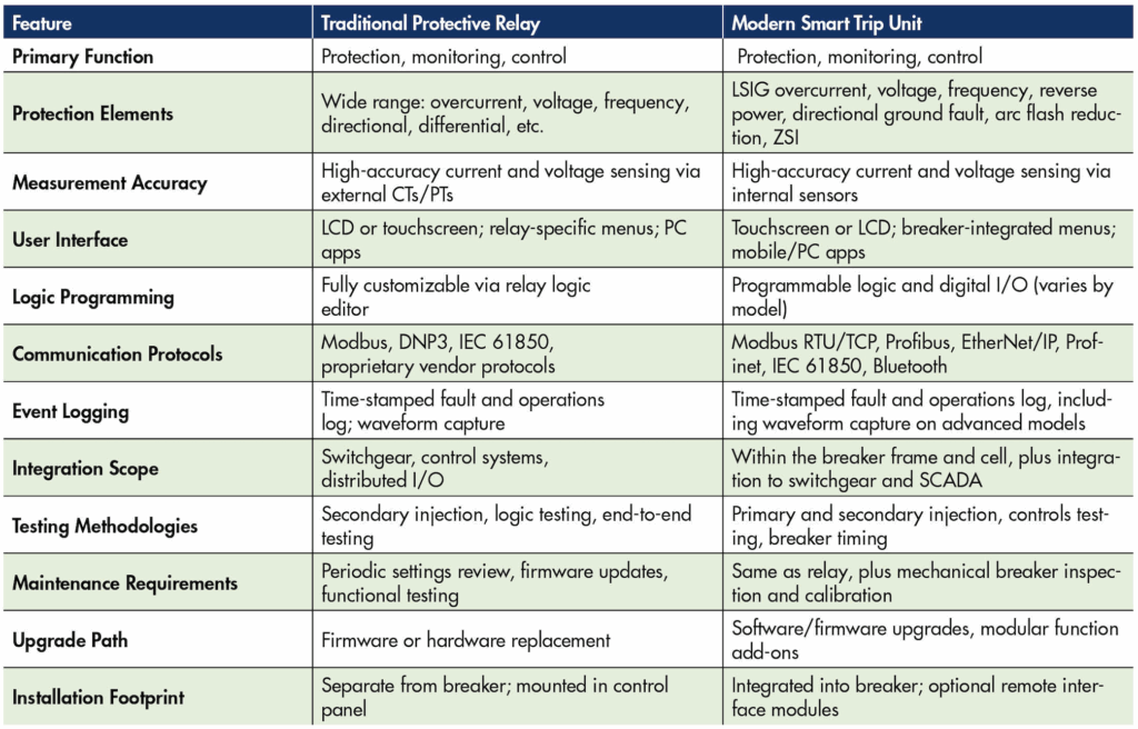
In comparison, protection relay architecture is quite similar. Instrument transformers provide current and voltage signals. Relays provide metering, computer-based interfacing, and digital, analog, and communication inputs. They record indications and events, produce direct trip commands, initiate communications-based trip schemes, and complete other logic-driven processes. Relays still maintain an edge over trip units in terms of customization, advanced fault recording, and I/O and logic processing, but the differences are becoming indistinguishable.
BRIDGING THE TECHNOLOGY PROFICIENCY GAP
Protection engineers have become well-versed in creating relay protection and control schemes and corresponding settings, and technicians are proficient in testing and troubleshooting these systems. However, even as newer trip units now have the same capabilities as relays, the approach to integrating and testing low-voltage protection systems is comparatively underwhelming.
As with any rapid technological shift, adoption lags capability. Barriers include:
- Cost concerns. Upgrading to more capable devices often carries a higher upfront investment.
- Reluctance to change. Engineers and facility managers may prefer familiar and proven equipment over newer, less familiar, and more complex systems.
- Knowledge gaps. Many engineers and technicians remain unaware of the required settings and the full range of features modern trip units offer.
This last point is particularly critical. Protection engineers integrating new trip units often limit their coordination studies to basic LSIG (long, short, instantaneous, and ground (LSIG)) pickups and delays, unaware of the required additional settings and available advanced functions that could dramatically improve system performance.
As a result, technicians frequently encounter:
- Mismatched settings between studies and available trip unit parameters (i.e., multiples of pickup vs. amperage-based pickup settings
- Desired setpoints that the installed trip unit cannot support
- Missing critical settings entirely (i.e., desired trip curve, external vs. internal ground fault current detection)
When this happens, test technicians must act as both troubleshooters and educators — informing clients and engineers of the discrepancies and working together to develop a solution.
CASE STUDY
On a recent commissioning project at a data center, the main low-voltage switchgear systems were comprised of circuit breakers with ABB Ekip Touch trip units. The commissioning technicians encountered an issue regarding ground fault protection, particularly how the trip unit senses ground fault current. In addition to the standard pickup and time delay settings, there is a setting for external vs. internal sensing. While many trip units rely on phase summation to calculate residual ground current and may even have inputs for an external sensor, they do not have a specific setting to differentiate between the two. The ABB Ekip Touch does. However, this was omitted by the engineer of record in the issued settings.
Although a review of system drawings and visual inspection revealed no external sensors, and a reasonable assumption could be made that the setting should be set to internal, it is ultimately the engineer’s responsibility to provide values for all available settings and for the technician to verify them.
Problems like these are an increasingly common occurrence as smart trip units become more widely adopted. Where there once were only basic protection functions and settings, trip units now have dozens of settings, and each one must be accounted for by engineers and technicians alike.
TESTING METHODOLOGIES
The similarity in function between trip units and relays means trip unit testing should mirror relay testing in many respects:
- Acceptance and commissioning testing
- Pickup and delay setting verification against coordination studies
- Functional checks of all protection elements
- Communication and SCADA point verification
- Primary injection testing*
- Confirms sensor accuracy, protection timing, and breaker operation under simulated fault current
- Secondary injection testing
- Allows verification of trip unit functions but varies widely in scope between test sets
- Functional logic testing
- Essential for advanced trip units with arc energy reduction, zone selective interlocking (ZSI), remote trip, or load-shedding schemes
- Firmware and settings verification
- Ensures correct versions and backups are maintained, just as with protective relays
*Some manufacturers are now releasing guidance suggesting that primary injection testing drastically reduces breaker life and is no longer preferred, emphasizing secondary injection as lower risk. An exception to this would be ground fault protection testing in accordance with NEC 230.95.
The standards for low-voltage circuit breaker testing are outlined in ANSI/NETA ATS, Acceptance Testing Specification for Electrical Power Equipment and Systems, Section 7.6.1.1 and Section 7.6.1.2. For breakers with smart trip units, instead of focusing on pickup and timing tests, greater emphasis should be placed on testing the integrated protection system in a manner more closely resembling Section 7.9.2, Protective Relays, especially when verifying trip unit communications, digital inputs, contact outputs, and SCADA functions.
BEST PRACTICES FOR RELIABILITY AND EFFICIENCY
- Involve protection engineers early. Ensure all trip unit capabilities are reviewed during design, not just basic overcurrent elements.
- Perform settings validation at commissioning. Cross-check the coordination study with the actual trip unit’s available settings.
- Train field technicians. Include both protective relay and trip unit programming in technician skill development.
- Document everything. Firmware versions, settings backups, and communication configurations should be part of the maintenance record.
- Use manufacturer tools. PC software (e.g., ABB Ekip Connect) or mobile apps (e.g., EPiC) can streamline configuration, testing, and upgrades.
CONCLUSION
The evolution of trip units from simple breaker accessories to multifunctional protection devices has transformed low-voltage protection. Modern trip units now rival — and sometimes replace — standalone protective relays in capability, requiring a shift in how they are specified, tested, and maintained. For engineers, technicians, and facility operators, the lesson is clear: If it walks like a relay, talks like a relay, and protects like a relay — it’s time to treat your trip unit as one.

Joel Wilbur is a NETA Level 4 Senior Technician and Regional Manager for CBS Field Services. A Navy Nuke veteran, he has been in the testing industry since 2007.