

If you ask five people to describe a microgrid you might get five different answers. But one universally required function that cuts across all the nuances of what can make a microgrid a microgrid is the ability to “island” from the grid while continuing to serve onsite electrical loads. Islanding is the process of disconnecting and later reconnecting to the grid. It is complex and specific to each microgrid project.
A Sequence of Operations document that was developed to aid in system design clarifies how a microgrid is intended to behave. In this article, we define common modes of operation for solar-plus-storage microgrid systems, explain the transitions from one mode to another, and provide a short list of key questions to ask early in the development process.
DEFINING A MICROGRID
There is no universally accepted definition of a microgrid (Figure 1). Instead, three essential features distinguish a microgrid from the broader electrical grid.

- The microgrid has an easily identifiable boundary from the rest of the grid. Electrically-powered assets within the boundary will remain active even when the rest of the grid outside the boundary loses power. The boundary could be a subset of circuits within a building, an entire building, a group of buildings, or an entire campus.
- Resources within the microgrid can be controlled together. Sophisticated controls are an essential ingredient in a microgrid. A typical control system includes many distributed controllers and sensors and a central supervisory control and data acquisition (SCADA) system to collect data and distribute instructions. The software behind the controls can balance the load by increasing generation or decreasing demand elsewhere on the microgrid, maximizing renewable energy usage, and minimizing other electricity costs.
- The microgrid is capable of functioning whether or not it is actively connected to the rest of the grid. In general, everything inside the microgrid boundary should operate normally without relying on grid power. However, the amount of time a microgrid can operate independently will vary based on the microgrid generation and storage capacity, the size of the microgrid loads, and local weather conditions, among other factors.
DEFINING MICROGRID SEQUENCE OF OPERATIONS
For the purposes of this article, let’s consider a hypothetical microgrid consisting of a PV solar array and battery energy storage system (BESS) designed to meet resiliency goals by providing full backup during a grid outage and otherwise supply as many of the onsite loads as possible with electricity generated from the PV array. Based on the project goal (resilience) and equipment (solar array plus BESS) we can derive three main modes of operation:
Normal Operation
The microgrid (Figure 2) is connected to the grid, which operates within the expected voltage and frequency ranges. Since we want to be ready for a resiliency scenario, the energy storage system is programmed to maintain above a reserve state of charge. Any excess electricity generation from the PV array will be used to meet instantaneous loads, charge the BESS further, or export to the grid.

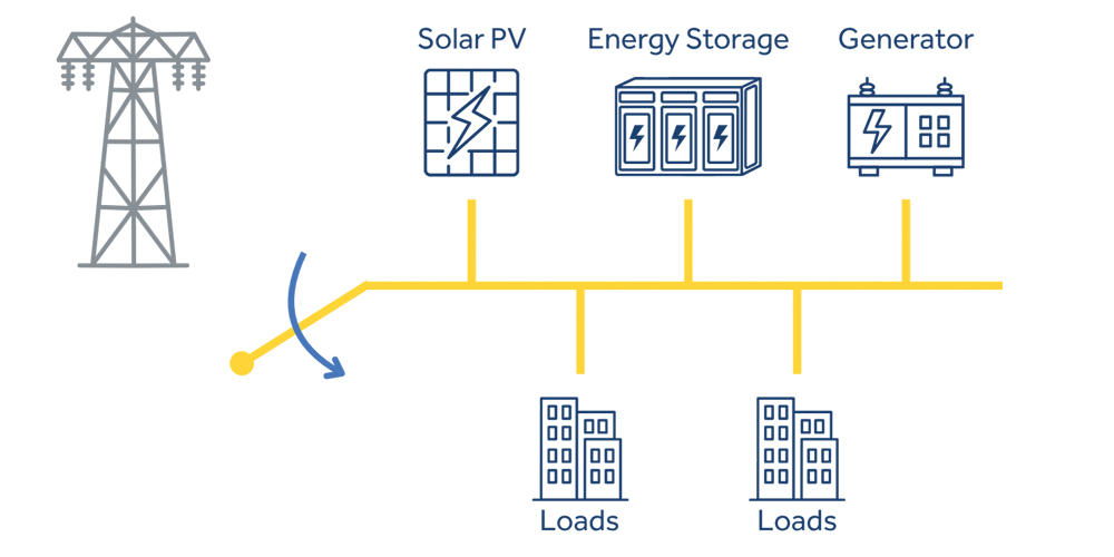
Grid Disconnection
The microgrid detects a grid outage (Figure 3) and undergoes the process of islanding. Once fully isolated from the grid, the solar array and BESS will become the primary power source for the microgrid. One of the BESS inverters will enter a grid-forming mode to provide a reference voltage and frequency for the entire microgrid system.
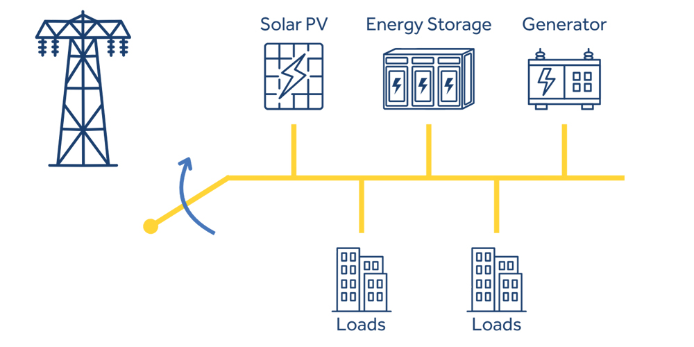
Grid Reconnection
Grid power returns, and the microgrid transitions from being a self-sufficient energy island to a parallel connection to the broader electrical grid after detecting grid stability (Figure 4). The solar and BESS inverters all enter grid-following mode, relying on the grid as a voltage and frequency reference.
Starting with these three core operating modes, we can document how the components of the microgrid are intended to work together. This forms the basis of the sequence of operations (SO) document.
SEQUENCE OF OPERATIONS DOCUMENTATION
Microgrid development is highly collaborative. The end user and system owner should kick off the project by defining performance goals. The developer and engineer of record will determine the best path to meet those goals while also adhering to AHJ requirements and technical constraints. The best way to ensure goals are met — and any changes are addressed — is through documentation.
When we design a microgrid system, we assume the system will perform certain functions. Using a conceptual sequence of operations (CSOO) document, captures those functions to verify alignment between the designer, the client, and other project stakeholders. We begin using the CSOO document with the 30% preliminary design, the point at which major system components should all be specified. At later stages of the development process, the client may choose to share the CSOO document with the energy management system (EMS) manufacturer, who would review and revise the CSOO and program the EMS accordingly.
Returning to our hypothetical solar-plus-storage microgrid system, a CSOO for the three primary operating modes could include:
- Normal operation. Export of excess PV to the grid vs. curtailment, routine BESS maintenance cycling, reserve state of charge for backup power requirements, and method of monitoring the grid signal for voltage and frequency anomalies.
- Grid disconnection. Method of grid isolation, including whether the transition is closed or open (see next section); when the BESS inverter will enter grid-forming mode; and the energy storage state of charge reference points.
- Grid reconnection. Method of detection of a stable grid; operations undertaken to reconnect to the grid.
ENGINEERING CONSIDERATIONS
Sequence of operations documents are customized to each microgrid project, but there are a few common variables to keep in mind.
Is an Open or Closed Transition Required?
In an open transition, the microgrid must fully break its connection to the grid before making a connection to other onsite generation sources. There will be a brief moment (on the order of a few milliseconds to a few seconds) during which the microgrid loses power during the transition. In contrast, in a closed transition, the microgrid establishes onsite generation sources as the primary power source (i.e., the BESS inverter enters grid-forming mode) before breaking its connection to the grid.
A closed transition is seamless, but the equipment required is far more complex and expensive. Closed transitions are required for emergency backup loads. Open transitions are much more common for everyday backup loads because the equipment required is cheaper, easier to procure, simpler to program, and will not risk back-feeding between sources.
Are Any of the Backup Loads Considered Emergency Loads?
NFPA 70–2023®, National Electrical Code®, defines an emergency system as:
“…a system intended to supply, distribute, and control power and illumination essential for safety to human life.”
If the backup loads for your microgrid fall into this category (e.g., lighting, heating, and cooling loads in a hospital), you must comply with more stringent code requirements, and your microgrid will require a closed transition to ensure power is never interrupted.
What Are the Microgrid Interconnection Requirements?
IEEE Std. 1547–2018, IEEE Standard for Interconnection and Interoperability of Distributed Energy Resources with Associated Electric Power Systems Interfacessets baseline requirements for grid-interconnected distributed energy resources such as solar PV and BESS. Utilities can apply their own regulations on top of the IEEE 1547 standard, such as California’s Electric Rule 21, Generating Facility Interconnections. All interconnection requirements must be adhered to during normal operation and must be factored into the grid disconnection and reconnection processes.
CONCLUSION
Microgrid sequence of operations documentation describes the common modes of operation and the methods by which the microgrid transitions between each mode. Using an effective conceptual sequence document ensures alignment between project stakeholders and acts as a basis for EMS programming.
REFERENCES
- NFPA 70–2023®, National Electrical Code®.
- IEEE Std. 1547–2018, IEEE Standard for Interconnection and Interoperability of Distributed Energy Resources with Associated Electric Power Systems Interfaces.
- California Public Utilities Commission. Electric Rule 21, Generating Facility Interconnections.

Lucas Miller is a Senior Engineering Consultant at Mayfield Renewables. He entered the renewables industry straight out of college by moving to Portland, Oregon, to join a PV contractor. Miller has since held many roles in the solar and energy storage industry, spanning marketing, market research, product development, and project coordination. In his current role at Mayfield, he brings his talents in research and writing and provides much of the leadership for Mayfield’s educational content development. He earned BS degrees in marketing and renewable energy engineering from the Oregon Institute of Technology.