

In power system protection, time has always been central—from coordinating relay trip times to selecting algorithms and schemes with the fastest trip times for fault clearing. Historically, however, time synchronization was largely an afterthought serving SCADA and event logging. That has changed with today’s digital substations.
This article explains how precision time protocol (PTP) based on IEEE Std. 1588 enables protection-grade synchronization and provides a practical blueprint for designing, validating, and commissioning a substation timing architecture.
TIME SYNCHRONIZATION IN SUBSTATIONS
In power system protection, time has always been critical—from coordinating relay trip times to selecting algorithms and schemes that minimize fault clearing time. Historically, however, time synchronization was largely a nice-to-have, an afterthought serving SCADA and event logging in the substation. That has changed with today’s digital substations. In earlier generations, each relay received analog current and voltage from instrument transformers, digitized these measurements locally, and made tripping decisions on its own sampling clock and settings. Now, relays may process signals that arrive already digitized and time-stamped by other microprocessor devices.
When multiple digitally time-stamped signals traverse the station communications fabric and converge in a protection relay, we must ask whether all signals are aligned to the same sampling interval and remain free of unacceptable errors from device clock offsets or network delays. More precisely, what level of inaccuracy is acceptable for protection purposes, and how should synchronization accuracy and status be monitored so that certain elements that depend on this are inhibited when sync status is lost or degraded?
As soon as the protection architecture depends on a time-synchronization scheme, that scheme itself becomes part of the protection concept. If the timing system fails or degrades, so does the greater protection system. Furthermore, does it become a single point of weakness, or has robustness and redundancy been deliberately engineered?
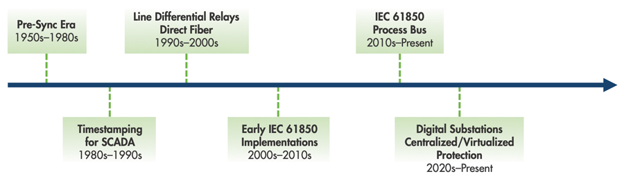
The timeline (Figure 1) shows how time moved from a background detail to a core element in digital substation designs. Until the 1980s, relays used local clocks, and time was mainly for event logging. In the 1990s, digital line differential relays over direct fiber offered better protection for the line than traditional schemes, but precise time alignment between terminals was required. However, this time sync was typically over direct fiber and not station-wide. In the 2010s, with IEC 61850 process bus and sampled values, timing shifted to a station-wide service often synchronized globally through a GPS antenna, passed through Ethernet switch hardware, and finally to the end device’s internal clocks, enabling multiple IEDs to be synchronized to a common time reference.
FROM LEGACY TO DIGITAL: WHAT CHANGED AND WHY IT MATTERS
Time synchronization has played a role in substations for a long time. What has now changed is the reason devices need to be synchronized to support the level of accuracy and availability. Historically, better time synch means better correlation of event records and SCADA logs. In digital substations, it directly affects how protection functions interpret and compare data.
With many modern schemes, protection elements depend on synchronized, time-stamped signals for proper functionality. When signals are time-stamped by different devices and later realigned in the relay, any synchronization error rides along with the data. If that error exceeds the element’s tolerance, the comparison can be biased enough to cause misoperation. Therefore, the synchronization status must be monitored, and selected functions must be blocked if necessary. At the same time, certain protection functions are not sensitive to the synchronization status of devices, such as overcurrent.
A practical approach is to actively monitor the synchronization status and/or accuracy and block only those protection functions that rely on tight synchronization, leaving others in service and re-enabling sync-dependent functions once acceptable conditions are restored. This remains consistent with the traditional goal of power system protection: Balance reliability with availability.
We often say a substation has “one clock (or two),” but in fact every microprocessor device—relays, merging units, gateways—has its own internal clock. The so-called substation clock is simply the dedicated time source whose primary role is to maintain high-accuracy time, distribute it to all those device clocks, and act as the reference clock for all synchronized devices.
For this article, we will refer to this network of clocks and the infrastructure it runs on as the substation timing system. Different time-sync
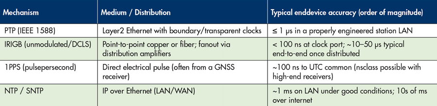
protocols such as IRIG-B, NTP, PTP, and 1PPS are used in substations. These protocols (Table 2) offer varying levels of accuracy, different mechanisms for distributing periodic synchronization messages, and different media on which the messages are sent.
Precision time protocol (PTP) has proven to be an ideal protocol for modern substations due to its accuracy and the fact that this packet-based protocol uses Ethernet as a medium, which is already present in modern substations. However, a system designer must ensure that the equipment is PTP-capable as well as tried and proven. As we’ve all come to learn, multi-vendor standards can be interpreted differently by different vendors.
PTP IN POWER SYSTEMS: THE ESSENTIALS
Precision time protocol (PTP), defined in IEEE 1588, was first published in 2002 as a protocol for synchronizing clocks in networked measurement and control systems. It is a packet-based method that distributes a common time reference over an Ethernet network. The reference clock in a PTP system is the grandmaster clock, typically synchronized to a GPS (or other GNSS) time source.
Within a PTP domain, the grandmaster periodically sends sync messages (often at one-second intervals in power profiles, though the rate can be configurable). The receiving devices, known as ordinary clocks or slave clocks, use these sync messages along with follow-up and delay-request and response messages to calculate the time offset from the grandmaster and the mean path delay through the network (Figure 2). Once these quantities are known, each device can steer its local oscillator so that its internal time tracks to the master time.

With t1 , t2 , t3 , t4 time stamps obtained and known by the slave clock, it can then calculate the mean path delay on the network between itself and the master. Note, this delay will be affected by the physical location of the end device on the network and influenced by the hardware that the messages must pass through.
Delay times

Offset

Time of Slave Clock

This synchronization mechanism runs continuously in the background, maintaining a high level of sync accuracy. In addition, another mechanism is running in the background to identify which clock will act as the grandmaster in implementations where multiple potential masters exist. This mechanism is defined as the best master clock algorithm (BMCA),whichcompares the values listed in Table 3 to determine whether a new grandmaster is elected.
Priority 1 and Priority 2 (Table 3) are configurable settings to influence a preferred clock to act as the grandmaster; other inherent or measured values and settings reflect the performance and status of the clock.

PROTECTION-GRADE ACCURACY: WHAT IS GOOD ENOUGH?
In protection, very-high synchronization accuracy is required so that samples can be realigned into the same time interval. What does “accurate enough” mean in practice? First, consider the sampling interval. IEC 61850-9-2LE and its successor, IEC 61869-9, specify 80 samples per cycle for 60-Hz systems:

The sampled values containing digitized current and voltage measurements are therefore sampled and published 4,800 times per second with an interval of 208.33 µseconds and transported over the station communications fabric. Finally, devices subscribe to these values and use them in their protection algorithms for tripping decisions (protection relays).
With most protection relays requiring 16–32 samples per cycle for algorithms (differential, distance), 80 samples per cycle are deemed sufficient for protection purposes with room for error. Therefore, adding a higher resolution would require higher processing and network bandwidth capabilities, with no real benefit for the overall performance of the protection system.
When these sampled values reach the protection relay, two things must be true:
- They are reassembled in the exact order they were taken, and
- The reference clocks of the measuring devices (merging units) and the receiving devices (protection relays) are aligned closely enough that the relay places each value back into the same 208.33 µs window.
If either condition is not met, the relay may end up comparing samples that were not taken at the same instant, and the resulting error can appear as a real difference in magnitude.
To ensure the sampled values frames are realigned in the proper order, IEC 61850 defines the smpCnt or sample count field, which is present in every sampled values frame. This field is a numerical value between 0 and 4,799 for each sample taken within a one-second interval. The publisher of this sample assigns the smpCnt, and the subscriber uses this value to reorganize the samples in the proper order.
To validate that the reference clocks of each device are accurate enough with respect to one another, we must rely on PTP. PTP synchronizes clocks to a common time reference (the grandmaster clock) and, in the power profiles, effectively defines the maximum acceptable offset as 1 µs for a synchronized device. Therefore, in a synchronized state, 2 µs is the maximum possible offset between two clocks. An additional field in sampled values defines the synchronization status of the merging unit at the time it took the sample. The smpSynch field is defined as one of the following numbers:
- 0 = internally synchronized
- 1 = local synchronization
- 2 = global synchronization
According to IEC 61850, a properly functioning digital substation implementation will rely on a well-synchronized substation timing system, achieved through precision time protocol. This substation timing system is a sub-system of the protection system, and just as other subsystems, including the protection settings or wiring, must be carefully designed, tested, and monitored, so must the substation timing system.
DESIGINING A SUBSTATION-GRADE TIMING ARCHITECTURE
Designing a substation-grade timing system requires careful engineering so that time synchronization does not become the Achilles heel of the overall protection scheme. Hardware must be selected from reputable vendors with proven, standard-compliant PTP implementations. The architecture should avoid single points of failure by providing redundant time sources and redundant paths. In protection, redundancy is a proven means of enhancing reliability; the same philosophy applies to the timing infrastructure.
Beyond hardware, correct operation depends on a solid understanding of the relevant PTP profiles for power systems (for example, IEEE C37.238 and IEC/IEEE 61850-9-3) and consistently configuring those profiles across clocks, switches, merging units, and protection relays. Parameters such as domain numbers, delay mechanisms, message rates, BMCA priorities, and holdover behavior must be coordinated so the timing system remains accurate enough under both normal and contingency conditions. If the accuracy is lost or degraded, then the protection settings must disable certain elements. This can be done by internal logic in the relay, configurable logic, or settings.
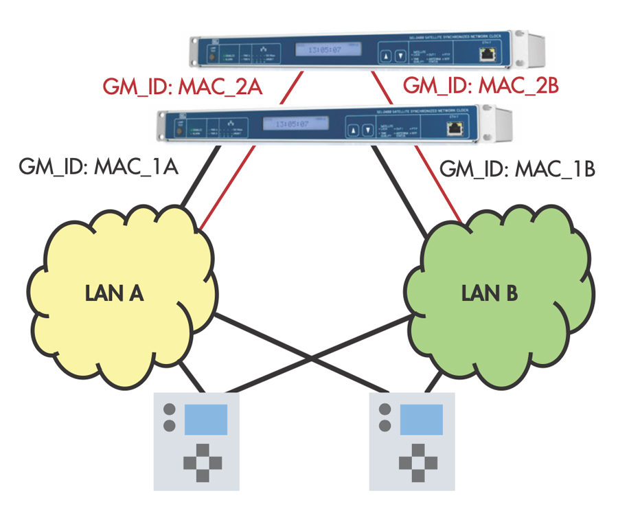
Figure 3 shows an example of a redundant substation timing system with two potential master clocks, redundant paths over the parallel redundancy protocol (PRP), and redundant ports on the end devices. A designer must understand how the devices handle redundancy.
COMMISSIONING WORKFLOW: HOW TO ENSURE IT WORKS, AND WHAT HAPPENS WHEN IT DOESN’T
At this point, it should be clear why the substation timing system must be treated as an integral part of the greater protection system. Before critical power system protection can go into service, it must be rigorously tested to prove it is fully operational and will perform its functions if it is called upon in case dangerous faults appear on the power system. It must also avoid any mis-operations that may lead to unnecessary power outages. Because the substation timing system underpins many of these functions, it must be tested, commissioned, and its failover scenarios verified before allowing the overall protection scheme to go into service.
A practical workflow to verify operation includes:
Step 1: Verify that grandmaster clocks are active, and performance is satisfactory.
Step 2: Confirm switches are properly configured and are not introducing unsatisfactory delays.
Step 3: Confirm end devices are synchronized and display this state.
Step 4: Perform a failover scenario: clocks switch over to the new time source, and alarms are displayed properly (ideally locally and to SCADA).
Step 5: Perform protection tests with a synchronized test set, confirming that appropriate protection elements are blocked when devices lose synchronization and re-enabled when sync is restored.
To perform Step 1 and Step 2, a tester will need insight into the timing statistics of the network, which can be achieved using a network-analyzing tool with PTP capabilities.
In Figure 4, the PTP sources on ports A and B of the analyzer show available grandmasters on the network and display their details. With this information, we can confirm the presence of PTP sources on LAN A and LAN B of the substation network. We also get details on the configuration, PTP profile, grandmaster ID, VLAN, grandmaster priority 1 and 2, clock accuracy, clock class, clock variance, etc. This information is also key if ever the substation timing system is not functioning, and the tester must troubleshoot.

For Step 3, we must have information on the mean path delay (Figure 5) discussed earlier, as an unsatisfactory mean path delay can be introduced by network switches or other network components. This time is measured and calculated by an end clock and is not advertised by the grandmaster.
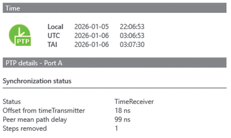
The same network analyzer shows the mean path delay over the network, which is measured and not advertised by the master clock. With this knowledge, we can pinpoint whether the grandmaster clock or the network is malfunctioning.
VERIFYING SYNCHRONIZATION STATUS AND FAILOVER
Step 3 and Step 4 can be performed in the same test plan. Step 4 is only applicable if there is clock redundancy and will require the main clock to be removed from the network, disabled, or forced into inferior status according to the BMCA.
One of the greatest benefits of the shift toward digital substations is the amount of information available to system operators and test engineers. As traditional signals are moved into digital form and transmitted over the network, they carry valuable information on the status, health, and quality of the signals themselves.
A great example of this, specifically for monitoring the synchronization status of devices, is the time master supervision logical node (LTMS) function defined in IEC 61850:
6.4.5.4 Time Supervision
Time supervision is the function responsible for communicating the status of the time synchronization function of an IED. The logical note LTMS has been introduced for that purpose. It allows to know important conditions with regard to time synchronization as the status of the communication channel with the time source of the time accuracy class according to IEC 61850-7-2.
The synchronization status of all devices in the substation can be checked locally in a manual process, but test tools also allow us to build test plans (Figure 6) to verify station-wide synchronization in a more automated manner.

To verify synchronization, the IEC 61850 test software can poll each IED (merging units and protection relays) to verify its synchronization status via the LTMS logical node. Instead of verifying this individually in a time-consuming manner, the system configuration language (SCL) file can be exported from the configured project and imported into the test software. This is yet another advantage of testing in digital IEC 61850 environments. Based on the imported SCL file, we can select the LTMS logical node from the signal list for each IED. Once this is configured, we can refer to it as our substation timing system test plan and perform the test.
A report (Figure 7) is then generated showing the synchronization status of each device from the signal list. The test plan can also be saved and used as a template. This will serve well once it is time to fail over from the primary time source and see how the substation timing system reacts.
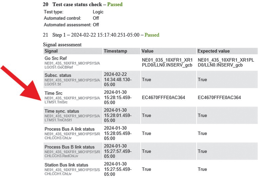
Earlier in the article, it was mentioned that redundancy should be implemented in the substation timing system to avoid a single point of failure in the greater protection system. Redundancy that has not been tested and proven is not true redundancy. This means that if redundant master clocks are installed to take over and act as a grandmaster in the event of a failure on the primary grandmaster, we must simulate this failure, witness the secondary clock takeover, and finally witness that all devices switch their internal time reference to the secondary clock. This can be done by reusing the same test plan, utilizing the LTMS logical node, and verifying the new GM Identity or MAC address displayed in Figure 7.
TIME SYNCHRONIZATION CONSIDERATIONS FOR PROTECTION TESTING
Step 5 will be performed in conjunction with the traditional relay testing. Consideration must be taken when performing protection testing in digital substations concerning the substation timing system. First, the protection relay under test must have all protection enabled and therefore must be in a synchronized state. The relay will likely require the sampled values produced by a test set to be synchronized (smpSynch flag = 1 or 2).
For this reason, it is often beneficial to synchronize the protection test set to the substation clock to obtain truly synchronized simulated sampled-value streams for test purposes. Additionally, since this is for testing, it is possible to force the value of the smpSynch flag to any of the allowable values shown in Figure 8.

It is important to ensure that appropriate protection elements are blocked under certain loss-of-synchronization conditions. Relay vendors handle this differently, and behavior may vary depending on the relay firmware version, but this is typically a mix of configurable settings, inherent functionality, and custom logic. This creates room for errors, so how the relays will block protection elements under loss-of-sync conditions must be understood and verified during commissioning.
CONCLUSION
In modern digital substations, time synchronization is no longer an accessory for SCADA and event logs; it is a core part of how sampled values, GOOSE messages, and protection relays work together. The substation timing system—grandmaster clocks, PTP configurations, time-aware switches, as well as relay logic and time-sync parameters—has effectively become a subsystem of the overall protection system, and it needs to be engineered with the same care as any part of the protection scheme.
Precision time protocol (PTP) provides the accuracy and flexibility needed to keep device clocks aligned in this environment, but good hardware alone is not enough. Designers must understand the relevant profiles (such as IEEE C37.238 and IEC/IEEE 61850-9-3), coordinate settings across the network, and avoid single points of failure by using redundant clocks, redundant paths, and appropriate supervision of synchronization status.
If something fails over, you want to know about it. When this is done well, the substation timing system supports reliable fault clearing and predictable protection performance, even during disturbances. It should never introduce a single point of failure.
Finally, the timing system must be verified and maintained. Commissioning workflows should include checks of the grandmaster performance, device synchronization status, and behavior during failover. The same test plans can be reused after firmware changes, network modifications, or device replacements, and tools based on IEC 61850 (including LTMS and automated test reports) make it practical to repeat these checks. In short, if digital substations are going to depend on time synchronization, then designing, testing, and documenting the substation timing system must be a standard part of putting protection schemes into service.
REFERENCES
- IEC/IEEE 6185093: Precision Time Protocol Profile for Power Utility Automation.
- IEEE Std. C37.2382017: IEEE Standard Profile for Use of IEEE 1588 Precision Time Protocol in Power System Applications.
- IEEE Std. 15882019: Standard for a Precision Clock Synchronization Protocol for Networked Measurement and Control Systems.
- IRIG Standard 20004 (and successors): IRIGB Code Formats and Characteristics; Vendor Application Notes on Accuracy and Distribution.
- J. Martin, Editor. RFC 5905: Network Time Protocol Version 4; General Admin Guidance on LAN vs WAN Accuracy Expectations. RFC Editor, June 1, 2020. DOI: https://doi.org/10.17487/RFC5905.
- GNSS Timing Receiver Documentation Discussing PPS Accuracy and Oscillator Holdover (e.g., GPSDO/OCXO Behavior). Available from multiple manufacturers.

Chris Larrivée joined OMICRON in 2020, where he is an advocate and specialist in the digitalization of substations and is highly involved in IEC 61850. He previously built six years of hands-on commissioning and testing experience in the power industry, managing and contributing to projects across Canada, the United States, Europe, and Africa. Larrivée holds an advanced diploma in electrical engineering technology from Algonquin College, a BS in electrical engineering from the Limerick Institute of Technology, and an MS in engineering from the University of Ottawa.