

“What’s in a name?” asked Shakespeare. The quote is so widely known because it’s so widely applicable. In the electrical industry, the terms “grounded” and “ungrounded” are commonly applied to electrical systems. They are often taken for granted or misunderstood. How can a grounding electrode be present, and yet the system is termed “ungrounded?” It is beneficial and productive to have a clear understanding of these terms, especially with respect to installation and enforcement.
A grounding electrode system is required at the first means of disconnect in order to render the cabinets and attached metallic equipment at earth potential, with the grounding protection extended to the ends of the system by means of equipment grounding conductors. This grounding connection will be integral in clearing ground faults. Without this in place, the system would have to rely on the earth as the fault return path. This is prohibited in the National Electrical Code (NEC®) Article 250.4(A)(5) for grounded systems and Article 250.4(B)(4) for ungrounded systems.
So if an ungrounded system must be grounded, how can it be an ungrounded system? The essential missing component that defines the ungrounded system is that there is no intentionally grounded conductor.
Article 100 defines ungrounded as:
…not connected to ground or to a conductive body that extends to ground connection.
No conductor is intentionally grounded, solidly or through resistance or impedance, resulting in theoretically no potential between conductors and ground. There can be capacitance between insulated conductors and other grounded components, such as enclosures, so that the system can be capacitively coupled (Figure 1).
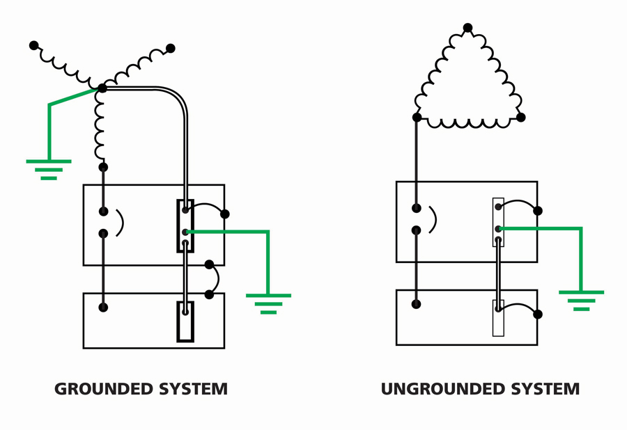
Figure 1: Grounded and Ungrounded Systems
With system AC grounding, the NEC distinguishes three categories:
- Required (250.20)
- Permitted (250.21)
- Not permitted (250.22).
The second and third categories are without a grounded conductor, but not without any grounding at all. Such systems are found in industrial and agricultural operations. Typical configurations are 240 V or 480 V, three-phase, three-wire, delta-connected. Higher voltage systems, such as 2,300 V, 4,600 V, and 13.8 kV, are also found in heavy industry.
In such systems, the occurrence of the first ground fault will not cause the overcurrent protective device to trip. This feature, however, applies to ground faults, not short-circuit or line-to-line faults. Such faults are typically high impedance and at unspecified locations. The system has accidentally become a corner-grounded delta system with little, if any, current flow.
A second fault, on a different phase, however, presents a problem. This is now a phase-to-phase fault on the system, and it will cause protective devices to open provided there is sufficient current flow. The worst case in this type of situation is when the second fault is a substantial distance from the first. This second fault could be line-to-conduit or enclosure (pull box, busway) in another part of the plant (Figure 2).
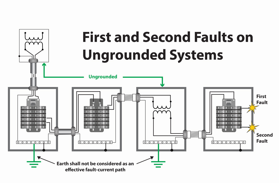
Figure 2: A Second Ground Fault on an Ungrounded System
This can create a relatively high-impedance current path that therefore can generate dangerous heat or arcing and sparking at loose joints or poor bonding. In addition, it can create significant shock hazards along the current path. Maintenance staff should locate and correct these initial ground faults before a second one occurs for safety and system continuity. Ground fault detection as described in NEC 250.21(B) also recommends routine maintenance of conduit couplings and locknut connections to enclosures in order to eliminate sparking.
DETECTING GROUND FAULTS
Ground detection equipment is available commercially and can be installed at the service entrance or in distribution feeder panels. Fault detection can be indicated in a number of ways so as to accommodate maximum effective operation of the facility. It can be accomplished by an overcurrent relay or shunt-trip circuit breaker. If continuous operation is required, fault occurrence can be indicated by visual and/or audible signals.
Sophisticated detection equipment is available to identify the fault’s location while the system remains in operation, enabling quick repair and reducing capital loss. Old systems used detector lights to indicate that a ground fault had occurred. A 7.5-watt indicator light would be connected to the lines through 18 kΩ resistors with a tap to each resistor to supply 120 volts to the lamp. The lamp would burn until its phase went to ground. At this point, there would be little or no potential across the lamp, and it would stop glowing.
More modern types of fault detection are now available. System ground connection is not required, not even through resistors. Rather, these new systems are equipped with transformers (windings) between the ungrounded conductor and the indication circuit. These indicators alert the maintenance crew of the existence of the fault so that maintenance can be scheduled during off-peak or other convenient hours. The plant can continue to operate with one phase grounded, with notable or even critical savings from lost production.
UNGROUNDED SYSTEM LIMITATIONS
Truly ungrounded systems exist only in the abstract. A capacitor exists whenever two conductors with a difference in potential between them are separated by an insulating material. Hence, ungrounded systems with insulated conductors in metallic enclosures are grounded to varying degrees by the distributed leakage capacitance of the system. A conductor installed in close proximity to grounded metal has capacitance between these two elements that is increased inversely to the distance between them.
For example, in a 600-volt system, the greatest sources of capacitance to ground are conductors in metal conduit and windings, as in motors and transformers. In these cases, conductors are separated from grounded metal by relatively thin insulation. The resultant capacitance is known as leakage capacitance, and the current from conductors to ground is known as leakage current or charging current. This capacitance s distributed throughout the electrical system but can be considered a single capacitance.
While the advantages of such a system have been mentioned, the disadvantages must also be taken into consideration. Transient overvoltages are not controlled. In time, these can degrade insulation and result in system failure. System voltages are not necessarily balanced or controlled. Similarly, system overvoltages are not controlled. These can result from lightning, switching surges, or contact with a high-voltage system. These overvoltages can be passed through transformers to the premise wiring. Destructive arcing burndowns from a second fault have also been mentioned.
These examples illustrate the potential problem of transient overvoltages in ungrounded systems. In an actual case on a 480-volt ungrounded system, line-to-ground potentials of over 1,200 volts were measured. A line-to-ground fault in a motor-starting autotransformer was traced, revealing intermittent arcing. This arcing fault had persisted for two hours, during which time 40 to 50 motor windings had failed.
Circuit-switching operations can also generate transient overvoltages in ungrounded systems, but these tend to be of short duration and do not exceed three times nominal system voltage. These overvoltages can produce system failures that are remote from the point of the fault in both distance and time. Weak points such as the windings of transformers and motors are particularly vulnerable.
FAULT LOCATION
This brings up the problem of fault location, which can be difficult. The first step is to check the ground detection indicator to identify the faulted feeder. Then, branch circuits are disconnected one at a time. This can be a tedious operation. By contrast, in a grounded system, only the faulted equipment has been taken off line by the overcurrent protective devices.
Because of the random nature of fault characteristics in ungrounded systems, it often happens that overcurrent devices are set above the current level of the fault. Destructive burndowns of electrical equipment can result. In addition, the first fault on a 480-volt ungrounded system causes the other conductors to rise to a level of 480 volts to ground, creating an additional shock danger to personnel. By contrast, in a 480-Y, 277-volt grounded wye system, the voltage to ground does not exceed 277 volts even under ground-fault conditions.
CONCLUSION
It is an important practical consideration to know the differences between grounded and ungrounded systems and to be able to weigh their advantages and disadvantages to install the best possible wiring configuration for your facility.
REFERENCE
L. Keith Lofland. “Are We Really Ungrounded?” IAEI Magazine, March 16, 2010.
 Jeffrey R. Jowett is a Senior Applications Engineer for Megger in Valley Forge, Pennsylvania, serving the manufacturing lines of Biddle, Megger, and Multi-Amp for electrical test and measurement instrumentation. He holds a BS in biology and chemistry from Ursinus College. He was employed for 22 years with James G. Biddle Co., which became Biddle Instruments and is now Megger.