

Electric vehicles are prominently heralded as the trend of the future, a vital part of many planned economies’ efforts to combat global warming, widespread pollution, and the squandering of resources. But there has also been negative publicity over safety issues like car fires.
The key to enjoying the best of both worlds — excellent performance under complete safety — is to practice diligent maintenance. Do not take performance for granted. It’s easy to ride the crest of a popular trend and overlook the details, but don’t. Become familiar with the possible safety hazards and industry-standard recommendations for preventing them.
The electric vehicle charger forms a dynamic link between the nearly infinite power of the electrical grid and the volatile potential of the car battery, possibly with the added potential hazard of a tank of gasoline only inches away in the case of hybrids. Be sure to maintain the safety of this vital link with regular and thorough maintenance of the charger.
EV CHARGER TESTING
Electric vehicle charger testers are available and dedicated to assuring the function and safety of the unique configuration of an electric vehicle charger. An electric vehicle charger tester should perform seven tests: four for safety, plus two operational tests and a check for nuisance tripping.
Regular safety maintenance and testing is critical.
It is a good idea to head off any potential dangers by testing the charger upon acquisition so it isn’t merely assumed to be fully functional because it is new.
Make sure the new charger meets manufacturing specifications. Do the same after any repair, and incorporate charger testing into any preventive/predictive maintenance program. It is important to perform the tests in a specific sequence, assuring safety first. Always remember, however, that the charger is an electrical connection between the vehicle and an electrical facility, such as a building service. That service must also be grounded, tested, and maintained.
Protective Earth
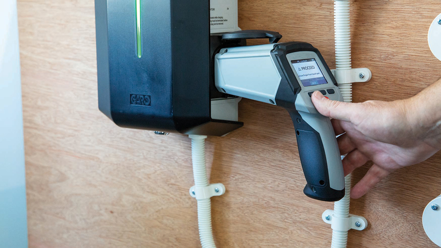
The first test verifies protective earth. The EV charger tester takes the place of the vehicle for the performance of the tests. The charger is plugged into the on-site power source, just as it would be if it were charging a vehicle.
The power grid, if not correctly utilized, can be a potential source of electrocution, fire, equipment damage, and other hazards. Therefore, the vehicle charger must maintain a protective ground, and this is not to be taken for granted. Ground connection can be lost while performing its designated function, as fault currents can open bonds even while being safely cleared. The next person using the faulted item — in this case, the vehicle charger — will be at unwitting risk should another hazard arise.
The charger tester will ensure that a proper ground is in place and functional. The tester applies a charging code to the charger to put it into a charging state. The protective earth contact test, which is accomplished through operator contact with a touch pad, will detect whether a ground connection is present (Figure 1).
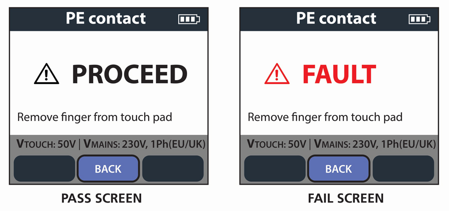
Figure 1: Initial Test Verifies Presence of Safety Ground
The test is not a genuine bonding test to verify the current-carrying capacity of the bond, but rather verifies the connection’s absence or presence. This is indicated by a PROCEED or FAULT message on the display. For maximum safety, any further testing of the charger is disabled, and a faulted bond must be repaired by a qualified electrician.
Protective Conductor Resistance
The second test is protective conductor resistance. This test verifies that exposed metalwork on the charger is effectively connected to the ground pin on the charger’s socket or plug so that any possible fault currents from electrical failure will be safely diverted into the grounding system — not through the body of an operator who happens to be in contact with the charger.
An alligator clip or probe is used to touch all possible points on the charger’s exposed metalwork. Therefore, this test is not required for chargers with no exposed metalwork or protected by double insulation. The tester measures the resistance to ground and displays it, along with a comparison to a safe standard of 0.5 Ω, which is typically indicated by a green check mark or red X (Figure 2). Failure must be repaired by a qualified electrician.
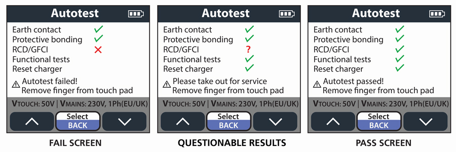
Figure 2: Pass/Fail Indicates Progress and Results
Trip Time and Touch Voltage Tests
The remaining safety tests are for touch voltage and trip time. EV chargers afford redundant safety protection through ground fault safety interrupters (GFCIs) or residual current devices (RCDs). These work by detecting an imbalance in circuit current. The differential could go to ground through a human being, or it could find an unwanted path through equipment, causing fire or electrical damage. To prevent that, the device trips and opens the circuit.
But GFCIs and RCDs are delicate devices that need to be checked. The charger tester applies a calibrated current matching the protective device’s rating and measures the time it takes to trip. The tester further assures that the trip time is fast enough to protect personnel from injury. Typical configurable parameters are voltage (230, 120), test current (30, 20, and 6 mA), and maximum test time (300 ms, 12.5 s, 5.59 s), with the tester indicating pass or fail. Another adjustment is angle of earth leakage current, either starting at the positive direction zero crossover (0 degrees) or negative (180 degrees).
Once the test has started, the tester puts the charger in charging mode and measures the output voltage. Next, a touch voltage test is performed to ensure that an inadequate ground will not raise the voltage to a hazardous level during testing. This test is adjustable at 25 V or 50 V. Earth leakage current is then measured and displayed.
Nuisance Tripping
Once the safety checks have assured that the EV charger can be operated without danger, a nuisance tripping test is performed. Extraneous currents such as the capacitive charging of long extension cables can be sources of nuisance tripping. This can be a hindrance to speedy and efficient testing. But once recognized, it can be eliminated by adjustment. The test applies a calibrated earth ground leakage current starting at approximately half the trip rating for the protective device in the charger, and then steadily increases the current until the device trips. The current at which the device tripped is displayed. The operator looks for a low trip value.
There are four ways to perform this test:
- A 230 V AC current is ramped up to 30 mA in 2 mA steps of 300 ms duration for 4.5 seconds.
- A DC current ramps at 6 mA for 2.5 seconds to prevent tripping of the AC response, then holds at 3 mA DC for 11.25 seconds.
- For testing 120 V equipment, a 6 mA AC test ramps up in 0.5 mA steps of 100 ms duration for 4.5 seconds.
- At 20 mA AC, a similar test ramps up in 1 mA steps of 100 ms duration for a maximum of 2 seconds.
Results are displayed in trip current, with 0-degree or 180-degree options available.
Proximity Circuit
A proximity circuit prevents the vehicle from moving during charging, an obvious safety requirement. The circuit provides a signal so the vehicle knows it is connected to a charger. When the charger is connected, the voltage on the proximity pin in the vehicle drops from 4.5 V to 1.5 V. The EV charger tester assures this will happen by simulating the circuit of the vehicle.
If the charger has separate connecting cables, the connector applies a proximity pilot (PP) resistance signal to the charger to indicate the rating of the connection cable. The maximum available current being indicated to the vehicle via the control pilot (CP) signal is adjusted accordingly. A charger tester verifies that this happens correctly by using cables with varied ratings. Test results are indicated by two symbols: a closed connector indicates proximity and a lock symbol indicates that the connection is latched.
Control Pilot Check
Finally, a control pilot check verifies the integrity of the communication between the charger and the vehicle. There are three main areas of communication:
- State of the vehicle/charger
- Maximum current to be drawn by the vehicle
- Whether digital communication indicates current
The first of these includes disconnected, connected, charging, charging with ventilation, CP to PE fault, and charger fault. The control pilot signal is a 1 kHz square wave with the charger state communicated using the signal voltage level. Maximum current and digital communication use are indicated by the signal duty cycle. The charger tester takes the place of the vehicle and allows the user to set the CP code. The tester then reads the code back from the charger as set out in Table 8 of IEC Standard 61851-1. This allows the user to verify the correct operation of the charger, ensuring that the charger responded as expected. In addition, testing the control pilot signal measures the charger output voltage and frequency.
Output charging voltage and frequency should be as expected for the utility supply to which the charger is connected. Polarity should read OK. Incorrect polarity is shown as INV. Maximum current should match the rating of the charger or connecting cable. Control pilot voltage, duty cycle, and frequency should be repeatable. The control pilot state read from the charger should match the code set for the test. A fault or error with the charger itself is indicated.
CONCLUSION
Compared to transformers, electric motors, building wiring, long runs of power cable, and a plethora of other pieces of electrical equipment, the electric vehicle charger may seem a simple device. Don’t let that allow it to slip off the chart for predictive/preventive maintenance. EV chargers have potential safety hazards that can be recognized and corrected.
An EV charger tester should be part of the electrical maintenance program. Both equipment damage and personnel injury can be prevented by testing and maintaining EV chargers. Customers and clients are afforded protection, compliance can be maintained with standards agencies like OSHA, and legal safeguards can be kept in place.
 Jeffrey R. Jowett is a Senior Applications Engineer for Megger in Valley Forge, Pennsylvania, serving the manufacturing lines of Biddle, Megger, and Multi-Amp for electrical test and measurement instrumentation. He holds a BS in biology and chemistry from Ursinus College. He was employed for 22 years with James G. Biddle Co., which became Biddle Instruments and is now Megger.