
Grounding and bonding are integral parts of an electrical system and must be properly understood, installed, and maintained for maximum safety and performance. Accordingly, the National Electrical Code© (NEC©) focuses on describing, defining, and regulating this element, specifically in Article 250 Grounding and Bonding of Electrical Systems.
Grounding electrical systems serve the dual purpose of limiting voltages that might otherwise rise to dangerous and destructive levels — from lightning strikes, line surges, or other disturbances — and stabilizing voltage to ground during normal operation. Proper grounding limits the danger of fire and damage and mitigates voltage levels that otherwise would be unstable and unusable.
PART I
The Code specifies which systems must be grounded, those that may be grounded but are not required to be, and those that are not required to be grounded. Though potentially confusing, correct application is simplified by identifying the applicable Code section by voltage and system type and then applying the rules. If the utility provides a grounded service, as is generally the case, then the premises’ wiring must also be grounded.
- Section 250.4 General Requirements for Grounding and Bondingdescribes the bonding of equipment and establishing effective ground-fault current paths. Bonding connects non-current-carrying parts, such as metallic equipment housings, to create a low-impedance path that permits current to flow back to the source in the event of a ground fault. Dangerous touch voltages developing between metallic casework and earth are avoided while overcurrent protective devices (fuses and circuit breakers) operate to clear the fault.
- Section 250.8 Connection of Grounding and Bonding Equipment describes seven specific methods that must be employed for connecting equipment and conductors for grounding and bonding. These include exothermic welding, pressure connectors, as well as machine screws and thread-forming screws that meet specific installation requirements.
PART II
Part II begins listing rules for grounding electrode conductors (GECs), main bonding jumpers, and system bonding jumpers.
Separately derived AC systems are subject to special rules. Determining whether a system is separately derived depends on whether the grounded conductor of the separate source remains connected to the grounded conductor of the service system. An illustration is a standby generator supplying loads through an automatic transfer switch. If the grounded conductor is switched in the transfer switch, then the standby generator becomes a separate source and the rules of this section of the Code must be applied. In such a separately derived system, there will be a system bonding jumper somewhere between the generator and the first disconnect. This jumper performs the same function as a main bonding jumper at the service. However, it is here defined as the “system bonding jumper.”
The Code provides sizing instructions in Table 250.102(C)(1) in Part V Bonding. These include rules for sizing grounded conductors, main bonding jumper, system bonding jumper, and supply-side bonding jumper for AC systems. Use Table 250.102(C)(1) for sizing grounded conductors, main bonding jumpers, system bonding jumpers, and supply-side bonding jumpers for AC systems based on the size of the largest ungrounded conductor.
PART III
Part III covers the grounding electrode and conductor. The grounding electrode is installed underground, and the grounding electrode conductor (GEC) connects it to the supply source. Eight components are permitted to perform grounding as part of the grounding electrode system. Each has specific requirements that include installation. For instance, copper rods fall under rod and pipe electrodes. They must be at least 8 ft (2.44 m) long and 5/8 inches (15.87 mm) in diameter unless listed. Various installation details are provided. Rods must contact Earth for 8 ft and be below permanent moisture level if practicable. The code provides installation details if rock bottom is encountered.
Table 250.66 specifies the size of the GEC based on the size of the ungrounded conductors. Connection requirements for grounding and bonding to electrodes are described as well as bonding jumpers around insulated joints in metal piping.
PART IV Intentionally Omitted
PART V
Part V includes 10 sections that address the variety and complexities of bonding. These include communication systems, services, and systems over 250 volts. The rules for bonding exposed structural metal and piping systems are of particular interest and detail.
PART VI
Part VI addresses the Equipment Grounding Conductor (EGC). Its purpose is to provide an effective, low-impedance ground-fault current path from the non-current-carrying metal back to both the source of supply and ground. This path must allow sufficient current flow to trip overcurrent protective devices. The Code requires that switchgear and switchboard frames, motor frames, electric signs, elevators, and cranes have their metal frames connected to an EGC.
- Section 250.118 Types of Equipment Grounding Connectors lists what can be used as an EGC.
- Section 250.119 Identification of Equipment Grounding Conductors explains how to identify the EGC.
- Section 250.122 Size of Equipment Grounding Conductors provides a table for sizing the EGC.NEC Table 250.122 covers the minimum size for equipment grounding conductors based on the rating or setting of the overcurrent device ahead of the equipment in the system.The EGC can be of copper, copper-clad aluminum, or aluminum wire type or busbar. The size of the EGC depends on the rating or setting of the overcurrent protective device ahead of the current. In dwelling units using Type NMC cable, the EGC can consist of a bare copper conductor. A copper conductor with green insulation is more common in commercial and industrial environments. Other common examples of EGCs are flexible and liquid-tight metal conduit, electrical metallic tubing, rigid and intermediate metal conduit, and Type MC cable.
PART VII
Part VII of the Code describes the proper and effective connection of EGCs.
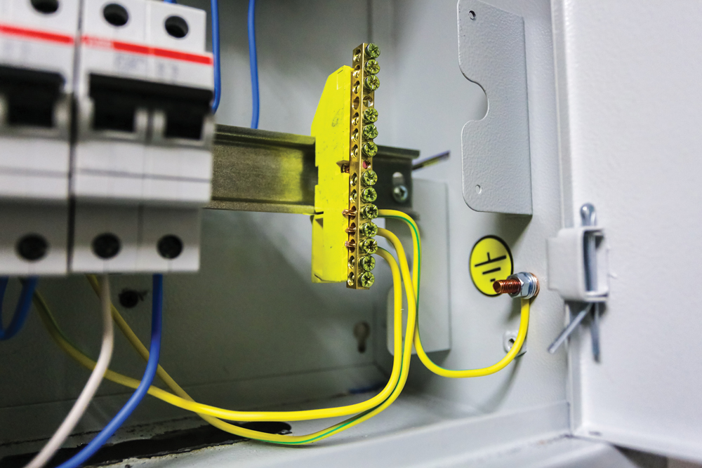
- Section 250.130 Equipment Grounding Conductor Connections covers connections made at the service equipment. Bonding the EGC to the grounded service conductor and the GEC is a requirement for grounded systems. This is accomplished by the main bonding jumper. Panelboard systems often have a green screw in the grounded conductor busbar which must be tightened down to make good contact with the enclosure.
- Section 250.146 Connecting the Receptacle Grounding Terminal and the Equipment Grounding Conductor specifies that a bonding jumper connect the grounding terminal of a receptacle (green screw) to the metal box. The metal box is further connected to the system EGC. Additional subsections of the Code point out where exceptions are made. For example, a metal surface-mounted box where one of the insulating washers is removed so that the yoke of the receptacle makes metal-to-metal contact with the box does not require a bonding jumper. Similarly, special provisions exist for self-grounding receptacles, floor boxes, and isolated ground receptacles.
PART VIII
Part VIII addresses DC systems, along with parts of Article 250 that are not specifically directed to AC systems. Generally, 2-wire DC systems between 60 V and 300 V used to supply premises wiring systems must be grounded. If a 3-wire DC system supplies premises wiring, the neutral must be grounded. The sizing of the GEC is different than that for AC systems. AC systems utilize Table 250.66 (see Part III) to size conductors.

- Section 250.166 Size of the Direct-Current Grounding Electrode Conductor describes the rules for DC systems. Ground-fault detection is required in ungrounded DC systems. In an ungrounded system, a single ground fault will not be recognized by the upstream protective device, as insufficient fault current returns to the source. If a ground fault develops on the opposite polarity conductor, a positive-to-negative fault will occur.
PART IX
Part IX discusses instrument meters and relays, including grounding and bonding requirements for current and potential transformers and relays typically found in switchgear. Secondary circuits of voltage and current instrument transformers must be grounded if the primary voltage is 300 V, but they must be grounded regardless of voltage rating if mounted in switchgear or switchboards. If instrument transformers, relays, and meters are operating at 1,000 V or less, they are connected to the EGC. If operating at more than 1,000 V, they are not connected to the EGC but must be isolated by elevation or some other means.
PART X
Part X addresses systems and circuits over 1,000 V. These systems are often connected to ground through an impedance. Solidly grounded systems, with no intentional resistance or impedance to ground, can be either single-point ground or multi-point grounded. The latter involves the neutral being grounded at more than one point. There are also rules for grounding service-supplied AC systems, including impedance-grounded systems. The grounding impedance must be installed between the grounding electrode itself and the neutral point of the supply and insulated for 57.7% of phase-to-phase voltage.
CONCLUSION
Grounding and bonding are easily confused, misapplied, or ignored. But they help keep electrical systems running properly and above all, safely. It’s not as simple as running a wire and connecting a rod. Be sure to understand the differences between grounding and bonding and implement them both according to the established standards and principles to minimize or eliminate potential danger.
REFERENCES
NFPA. NFPA 70, National Electrical Code® (NEC®), 2023 Edition.
Randy Barnett, NTT Training. “10 Sure Ways to Tell the Difference between Bonding & Grounding,” EC&M, August 2022. Accessed at https://www.ecmweb.com/basics/bonding-grounding/article/21247240/the-basics-of-grounding-bonding-electrical-systems.

Jeffrey R. Jowett is a Senior Applications Engineer for Megger in Valley Forge, Pennsylvania, serving the manufacturing lines of Biddle, Megger, and Multi-Amp for electrical test and measurement instrumentation. He holds a BS in biology and chemistry from Ursinus College. Jowett was employed for 22 years with James G. Biddle Co., which became Biddle Instruments and is now Megger.