

Over the past decade, we’ve gained critical insights into partial discharge (PD), recognizing it as a real issue that can lead to catastrophic equipment failures. We’ve also developed on-line and off-line methods to detect PD. Yet many still find it unclear why partial discharge occurs and inconceivable that something as simple as a poorly positioned tie-wrap can bring down a data center.
While the technical explanation for why partial discharge occurs involves electric field strength, geometry, and intricate insulation properties, it’s difficult to make an assessment unless you can do finite element analysis in your head. What we need is a clear understanding of what not to do.
This article shifts the focus to practical construction techniques that contribute to partial discharge. It covers real-world examples of switchgear and cable assembly errors that commonly lead to PD. With this knowledge, readers will be better equipped to construct reliable, PD-free substations.
Total discharge (catastrophic flashover) is a failure of an insulation system to withstand the voltage applied to it. Partial discharge is the failure of part of the insulation system to withstand the voltage applied to that part. The bold phrase in the previous sentence is the trick to understanding where the partial discharge will occur. The overall insulation system is intact (for now) but the part flashing over will eventually lead to catastrophic failure.
It all comes down to relative permittivity and withstand capability. Here are two common values:
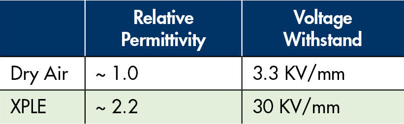
Let’s examine a simplified example. Assume we have XLPE insulation (30 KV per mm withstand). Let’s build a system with two conductors, each with 1 mm of insulation, tightly pressed together. Using a peak voltage of 42 KV, we have 21 KV across each 1 mm insulator and are therefore well below the breakdown voltage of XLPE. Now, let’s move the cables 1 mm apart. We have sufficient insulation and additional air space, and air is an insulator, so we’re good now, right? In fact, shouldn’t we be good at 60 KV+3.3 KV or 63.3 KV?
In actuality, the different permittivity of the materials causes the voltage distribution to be uneven. The voltage across the air gap will be 22 KV, and each XLPE insulator will have 10 KV. Flashover would occur because 1 mm of air could not withstand this voltage. XLPE insulation would not flash over, so we would have partial discharge on each positive and negative half-cycle of the voltage sinewave.
With AC voltage, the air gap would discharge long before you got to peak voltage (that’s why PD pulses occur before 90 and 270 degrees). This simplified scenario doesn’t account for everything but it demonstrates that the obvious answer isn’t always correct. Various other circumstances can result in partial discharge. Understanding the causes and recognizing typical problem areas can help us do a better job of building and inspecting switchgear.
AIR GAPS WHERE THERE SHOULDN’T BE ONE
As described above, a small air gap — even between insulators — can cause PD. Air gaps can exist in many locations.
- An unshielded wire running through an oversized grommet or hole in fiberglass panel board (Figure 1)
- A busbar going through an oversized passthrough bushing or hole in an insulating panel (Figure 2)
- A busbar resting unevenly on an insulator
- A loosely fitting boot on exposed bus connections
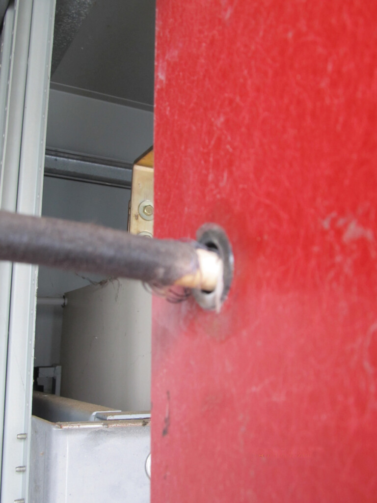
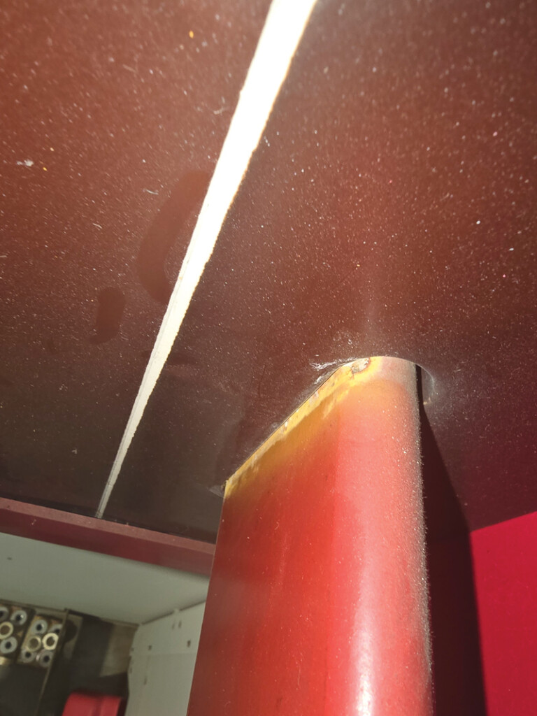
Use the correct grommets and bushings to ensure that small air gaps do not occur. Do not allow improperly fitting holes. A common solution is filling gaps with room-temperature vulcanizing silicone (RTV) of a similar or higher permittivity. Higher permittivity will result in less voltage across the RTV and more across the insulation (where it belongs).
INSUFFICIENT AIR GAPS
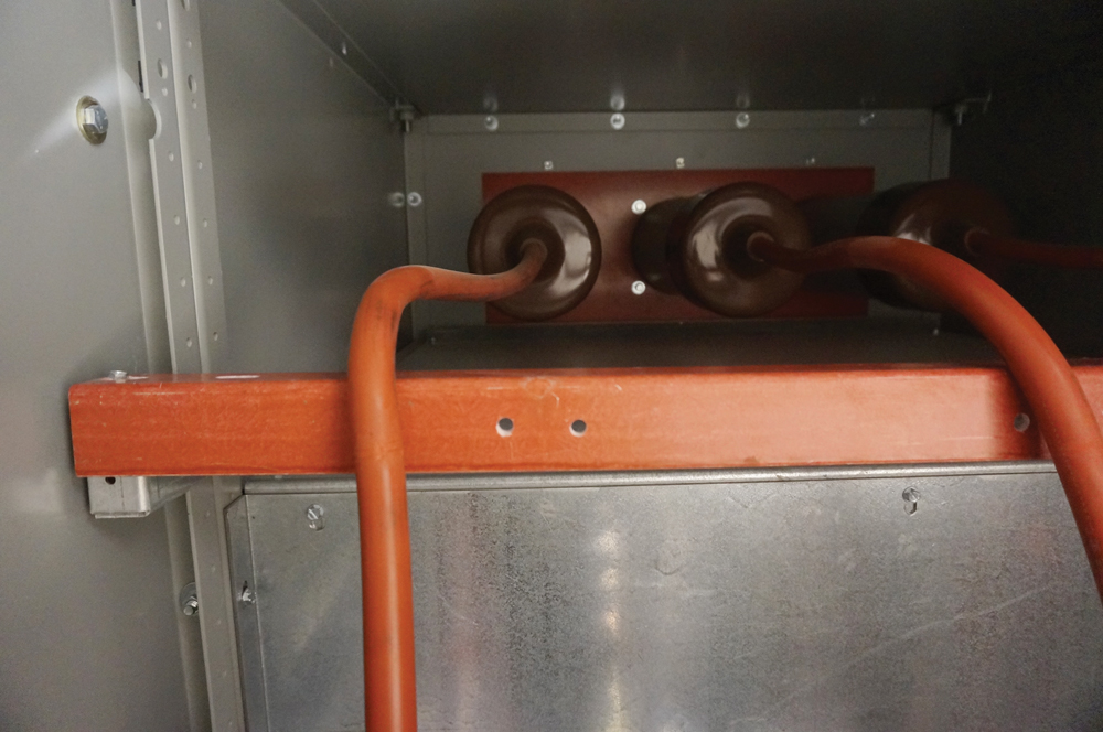
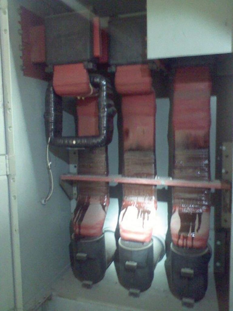
Situations with small air gaps are worse than no air gaps, but large air gaps are desirable. Air-insulated switchgear, by definition, uses large air gaps to provide adequate insulation between conductors. If those air gaps are insufficient for the voltage field — such as physically touching boots (Figure 3a) or MV cables from the transformer windings (Figure 3b) — discharge could occur over time.
Note that the transformer in Figure 3b likely passed all manufacturer and third-party NETA testing. Fortunately, this premature failure was caught prior to failing and was quickly remediated. Other similar equipment onsite was inspected, and additional units also exhibiting PD were found and promptly remediated.
It is necessary to look at minimum spacing under all conditions. Keep in mind that the withstand capability of humid air is as little as one-third that of dry air. Wires droop over time, expand, and move with higher current. Moving switchgear parts can also violate air gaps minimum clearances.
WRONG MATERIALS IN HIGH-VOLTAGE FIELDS
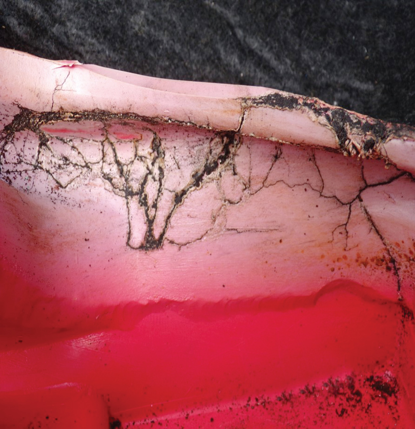
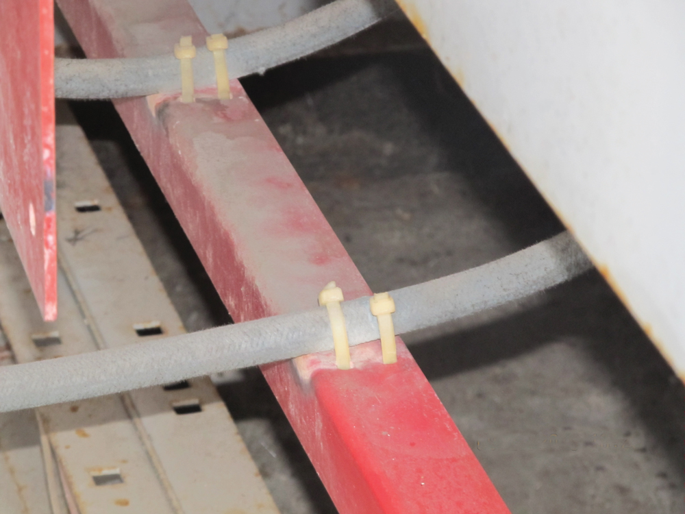
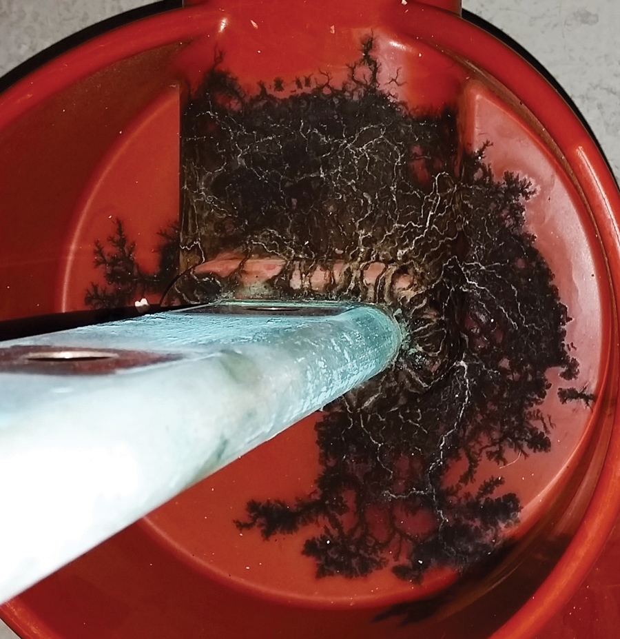
The natural reaction is to tie-wrap cables so they never move — but wait! We love tie wraps as much as any electrical guy, but they can cause big trouble in medium-voltage systems. A good insulation system has materials with known permittivity, good voltage withstand, high tracking and humidity rejection, and engineered geometry. Then someone goes in with a tie wrap they bought at Home Depot and cinches it nice and tight and there goes all that engineered goodness. Figure 4 shows tie wraps binding an unshielded cable to a fiberglass insulator. The resultant PD is evident. If the tie wrap itself isn’t the issue, the fact that we’ve bundled this wire close to something it shouldn’t be is another problem.
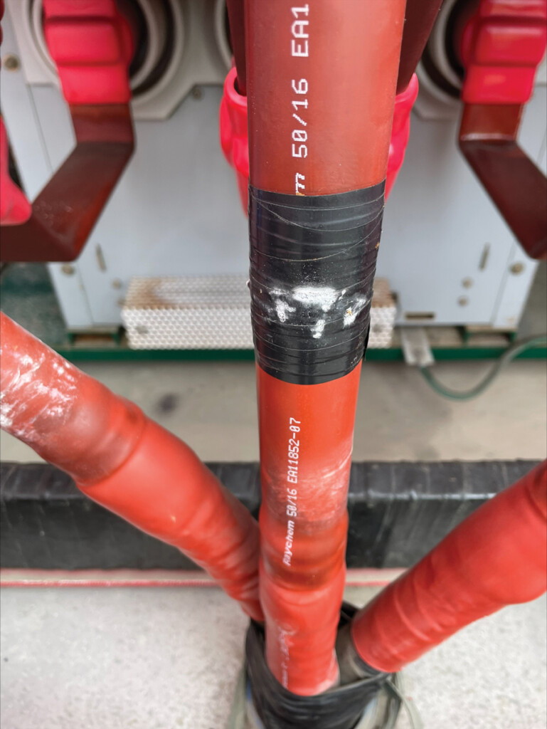
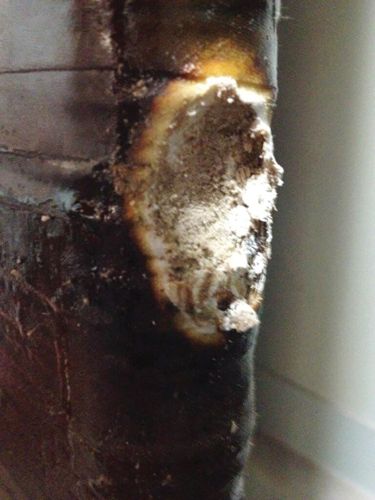
Another favorite is to add electrical tape to unshielded, insulated cables. Phase identification via colored tape has been around since Edison, and putting tape on the outside of a cable termination beyond where the shield is removed is a typical mistake. The outside of a termination is a high-field stress location, and tape will not offer the same permittivity as the outside of the termination. All tape, labels, paint, etc. on cables should go on the shielded portion. In Figure 5, black phase ID tape has caused PD.
By now, you should be getting the hint that medium- and high-voltage fields are easily influenced and need special attention. Using the wrong material can affect the field or the withstand ability of the insulation. This applies to solids as well as pastes like RTV or grease. Be careful with substances such as RTV or tape left in place or used temporarily, such as cleaning wipes. Cleaning wipes specific to electrical equipment should always be used as they are designed to not leave any residue that might result in tracking (surface PD).
POOR CONDUCTOR AND INSULATOR GEOMETRY
The electric field between conductors and ground is highly affected by the geometry of anything in that field other than a perfect insulator. The higher the permittivity value, the more it is affected. A conductor has an infinite permittivity, so it has the most effect.
A classic example is a sharp point on outdoor gear that results in corona discharge. For example, a wire going through a cable clamp with one strand of wire sticking out of the other side of the clamp will cause concentration of the electric field. If it’s high enough, the air will break down and discharge. The characteristic 60-Hz buzz and smell of ozone tell us this is happening. This issue doesn’t usually lead to failure outside because the ozone and nitrous oxide dissipate. However, in an enclosed compartment, the nitrous oxide turns into nitric acid and damages insulation.
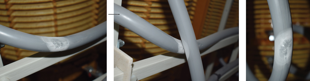
While corona is common, surface and internal discharge can also result from geometric issues. It pays to keep a sharp eye (pun intended) out for sharp edges on conductors or sharp interfaces on insulators. Two insulators touching at a small spot can concentrate the field and cause PD. Figure 6a shows a wire crossing a bracket with a sharp contact point. The PD was audible at initial energization and significant damage to the cable was visible after 4 months.
Another geometric effect is where corrosion appears on a smooth conductor. The pits and points of corrosion have sharp edges that can cause localized field concentrations. The corroded bus bar should be replaced whenever practical. Figure 6b shows an additional example of geometrically induced PD due to poorly installed ground braids that were zip-tied to the energized conductor.
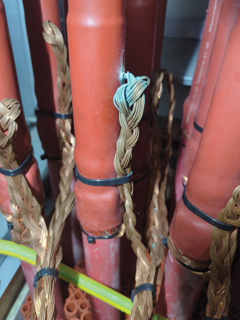
These ground braids created a sharp angle and an easy path to ground for an electric field from the energized conductor. This switchgear had passed all factory testing (as expected since cables were not installed yet), NETA testing, and commissioning tests. Visual inspections did not note, observe, or identify this potential partial discharge issue that was being created. Numerous other braided cables within the same section or the same switchgear lineup also showed identifiable partial discharge activity. Any affected cables were promptly repaired onsite to prevent this future short-circuit fault.
HIGH HUMIDITY AND SALT AIR
High humidity is a concern due to its impact on withstand voltage but there are additional concerns. When an insulator is unevenly coated in hydrophilic (water-attracting) contamination, you can get dry band discharge. The uncontaminated sections of the insulator tend to be hydrophobic (water-repelling), so the insulator has dry and wet areas that are insulating and conductive. This disturbs the field distribution and leads to discharge across the dry bands.
This is a real problem for outdoor insulators in areas of contamination. Salt-laden air deposits on insulators can form dry bands, and regular washing is the only real remedy other than building substations away from coastal areas, which isn’t practical. In these environments, overrated insulators will survive better than those used close to their rating.
Indoor substations should be designed to limit exposure to high humidity levels. Rapid changes in outdoor temperature can cause the air inside the substation to have high humidity and even condense. Condensation is best eliminated by using space heaters. One surprisingly common problem is that heaters are installed but often not turned on. Dehumidifiers can also be used to keep humidity low.
It goes without saying that water intrusion can result in high humidity. Conduits, basements, leaking roofs, etc., are all problem areas that should be avoided. Proper construction and inspection are necessary to keep any water leaks from perpetuating.
The worst example I’ve come across was an island substation with lots of PD induced by salty, humid air. I asked where the humidity was coming from, and the owner lifted a piece of plywood covering a hole leading to the substation sump. The hole was not only full of salt water but also had tiny fish swimming around. A good rule of thumb: If there are fish in your substation, the humidity is probably too high. Figure 7 shows the 10-year-old switchgear from that substation.
COLLECTED DIRT AND DUST
It is common practice to clean the horizontal surfaces inside switchgear during shutdowns, but it may not be fully understood why minor levels of dust are an issue. It comes back to humidity. Dust is often not conductive and is therefore not a concern for flashover, but it is very good at retaining any moisture that may occur. Imagine a flat surface such as a fiberglass brace between vertical busbars in a cabinet. The voltage distribution along the brace between phases is initially pretty even, but as dust accumulates and humidity collects, sections become conductive, totally disrupting the voltage fields. Figure 8a shows the result on the edges of the busbar where the brace was mounted. Figure 8b shows the bracket and the resulting damage. Partial discharge and flashover are concerns where the dust may be conductive (coal-burning plants, steel mills).
FLOATING METAL
If a little bit of dust and humidity or even a tie wrap in the wrong place can cause a problem, imagine a hunk of metal in the wrong spot. If it’s grounded and too close, you have an air gap or possibly a flashover problem. If it’s floating, you might not have a flashover risk but you have certainly disturbed the voltage field. The floating metal typically receives a partial discharge from the conductor, which will raise it to the line voltage and then discharge it to ground.
Floating metal can be caused by loose hardware making poor electrical contact. Remember, it doesn’t have to be in the current path; it could be a bracket on the side of the breaker mechanism. If it’s in the current path, it will show up as heat on an IR scan, but if it’s outside the current path, it won’t get hot. In extreme cases, the hardware backs completely out and the bracket is left on the bottom of the cabinet. Corrosion between conductive pieces can also leave a floating part. Be mindful of dissimilar metal connections or any aluminum connections. Make sure they are tight, and use any antioxidant recommended by the manufacturer. In the same vein, corrosion caused by water intrusion or high humidity can cause loss of contact and floating metal.
In a worst-case scenario, a technician left a plastic bucket of tools inside the cable compartment of the newly energized switchgear. Fortunately, this switchgear had full-time on-line PD monitoring, so the mistake was quickly caught.
CONCLUSION
Many additional causes of PD exist, but if you can address all the causes listed above, you will be well on your way to higher reliability. One last tip: Take a video of each compartment before you close it. Down the line, it might help you diagnose a cabinet that is showing PD while still on-line.

William G. Higinbotham served as President of EA Technology LLC, a company he founded in 2013, until December 2024. In this capacity, he managed the overall operations of the organization, which represents EA Technology’s activities across North and South America. His responsibilities included leading sales, service, support, and training initiatives for partial discharge instruments and condition-based asset management systems. Higinbotham now serves as Chief Engineer, overseeing technical support for customers within his assigned territory. Before his tenure at EA Technology, Higinbotham served as Vice President of the Research and Development Engineering group at RFL Electronics Inc. from 1988 to 1994. His work there encompassed corporate management, new product development, manufacturing engineering, and technical support. An active contributor to the electric power systems field, Higinbotham is a Senior Member of IEEE and has co-authored several IEEE standards related to power system protection and communications. He is a published author, contributing to several industry journals, including NETA World, and technical papers, and holds a patent in this field. Higinbotham earned a BSEE from Rutgers University’s School of Engineering in 1984. He began his professional career in biomedical engineering, where he worked for four years before joining RFL.

Jay Prigmore, PhD, PE, is an Electrical Quality Engineer, Sr. Technical Program Manager at Google LLC. He was previously employed at G&W Electric Company where he was responsible for short-circuit protection devices and their manufacture and applications. Prigmore has given IEEE invited lectures on arc flash mitigation techniques and developed a peer-reviewed arc flash mitigation device that won “product of the year” in electrical safety. He has testified more than 15 times in U.S. litigation and international arbitration courts related to incident investigations. He is a founding member of NFPA 78 and NFPA 1078, which provide guidance on performing electrical inspections and the qualifications of electrical inspectors, respectively. Dr. Prigmore has authored prior ESW papers and published IEEE articles on solid-state circuit breakers and incident energy reduction techniques. Dr. Prigmore presently holds twelve professional engineering licenses and was the 2024 IEEE Electrical Safety Workshop Chair. He received his BS in electrical engineering from Lamar University and an MS and PhD from Arizona State University.