Most of today’s available testing devices use various cables and sources to measure timing and contact resistance in high-voltage circuit breakers (HVCBs). Most have only one source for resistance measurement, so the resistance of each phase is measured individually. This implies that it is necessary to change the connection to the main circuit breaker several times during testing, which requires a substantial commitment of time and effort when dealing with high-voltage circuit breakers.
The proposed approach utilizes the same sources and cables for timing as well as contact resistance measurement. The approach was validated via real-world field testing on a 400 kV high-voltage circuit breaker, providing comprehensive results and analysis.
CONVENTIONAL METHOD
Among the essential components of any electrical power system, the circuit breaker stands out with its reliability being paramount. Therefore, the primary role of the specialized on-line and off-line measurement systems employed to assess circuit breaker condition is to detect any deviations in the breaker’s operating characteristics.
The most common method for detecting malfunctions in circuit breakers involves timing measurement, which evaluates the switching time of the breaker operations. During this process, the measured results are compared with the specified operating values recommended by the original equipment manufacturer (OEM). However, this approach has limitations in identifying all types of failures, partly due to the relatively low occurrence rates, averaging approximately six failures per 100 circuit breakers per year. To complement this method, other tests such as resistance measurement, dynamic resistance measurement, and movement measurement during operation are conducted to provide a more comprehensive understanding of potential failures.
Timing tests and contact resistance measurements, together with coil current and motion measurements, are recommended by international standards including IEC 62271-100, High-Voltage Switchgear and Control Gear – Part 100: Alternating-Current Circuit-Breakers. If a high-voltage circuit breaker’s mechanical operations don’t meet the manufacturer’s specified operating time limits, it risks being unable to effectively extinguish an arc during the making or breaking process. This leads to rapid deterioration of the circuit breaker’s condition and ultimately to unsuccessful interruption of a fault current and, consequently, adversely impacting the reliable operation of the power system. .
Assessing the condition of the circuit breaker involves meticulously measuring operating times to validate its integrity and operational efficiency. To achieve this, the authors have used graphical representations in terms of voltage drop to visually illustrate the intricate process of the breaking element’s operation (open or close operation).
NEW APPROACH — DYNAMIC RESISTANCE MEASUREMENT
In the field of circuit breaker testing and condition assessment, the adoption of new approaches and testing methodologies often precedes their establishment as industry standards. One such innovative approach is dynamic resistance measurement (DRM). This method produces comprehensive data sets that include a time series acquired during the making or breaking of the circuit breaker. The time series includes the movement of circuit breaker contacts recorded by appropriate motion sensors, along with voltage drop across the contacts and the injected test current which provides sufficient data for computation of the dynamic resistance throughout its operational cycle.
Beneficially, DRM can be conducted on fully assembled interrupting chambers. This method often leverages the initial closed state of the breaker to be able to perform the DRM. Utilizing the high-power current source makes it necessary to use weighty testing leads to obtain the appropriate connection.
It’s important to emphasize that the primary objective of DRM testing is to assess the condition of arcing contacts. When a CB operates, arcing contacts will close first during the closing operation; during the opening operation, arcing contacts will open last, meaning that the arc will be caught at the arcing contacts to preserve the main primary (current carrying) contacts. This causes deformation and erosion of the arcing contacts due to the arc formation. These potential arcing contact deformations and structural deviations cannot be detected by timing and contact resistance measurement tests alone. This shows the importance and benefits of the DRM test for assessing the condition of the arcing contacts. The condition of the arcing contacts can also be assessed by visually inspecting the dynamic resistance time series or by extracting the quantitative numerical indicators such as arcing contact overlapping time and arcing contact wipe length (overlapping distance), as well as by comparing the obtained results with those from other poles or with previously obtained reference results.
To perform the DRM test, car batteries have initially been used as a DC source. The deficiency of this approach mainly revolves around safety due to the chemical nature, weight, and the limited amount of energy. Some authors, including Ostojić and Levi, proposed using a micro–ohmmeter as a power source for DRM testing on dead tank circuit breakers, which provides satisfactory results with better safety conditions for operators. Additionally, since conventional micro-ohmmeters are powered by the power grid, this usually imposes additional noise into the recorded values and time series. This has been improved by using battery-powered test modules that yield a significantly better signal-to-noise ratio. This is reflected in terms of cumulative error in the computation of the dynamic resistance based on the acquired voltage drop and injected test current.
While a timing test incorporating coil current monitoring and motion measurement is effective in detecting mechanical maladjustments or signs of wear in the main contacts, operating mechanism, or other subassemblies, it is also essential to perform static resistance measurement (SRM) and DRM tests for a more comprehensive assessment of the state of the main and arcing contacts.
WHICH RESOURCES ARE OPTIMIZED?
Circuit breaker testing can be divided into three main parts: preparation, testing, and result analysis. Test preparation takes the most time and is where time and financial resource consumption could be optimized. Safety conditions during CB testing are considered a high priority followed by the time spent on testing and results analysis.
This paper offers a measurement method that can optimize the aforementioned resources. One of the most important advantages of the proposed principle is the so-called all-in-one cable connection for performing all tests: timing, static resistance measurement, and dynamic resistance measurement. Since the test preparation in terms of establishing proper lead connections is dominant, the proposed approach of using the one-set-up lead connection and a battery-based power source will optimize this stage significantly. The reduction in testing time is directly related to minimizing the testing cost as well as reducing the potential threats and injuries to testing personnel.
This fact is supported by the data presented in K. Obarcanin and R. Ostojic. The number and length of test leads increase as the rated voltage level of the HVCB under test increases (Table 1).

At least four leads must be connected per pole: two current cables and two voltage measurement cables. Additionally, for a timing test, a connection must be made to the control circuit using coil control cables (at least one lead for opening, one lead for the closing coil, and one lead for voltage supply). The cables used for generating high DC currents are significantly thicker and heavier than standard measuring cables. This adds complexity to test preparation, increases the time required for cable connections, and heightens safety concerns. In practical situations, there is a risk of cables becoming tangled or intertwined, potentially resulting in heavy cables (weighing between 5–15 kg) falling from elevated positions.
Furthermore, the ends of the test leads are secured with clamps, adding to their overall weight. Connections are typically made from crane baskets, which further raises safety issues as crane movements can inadvertently catch and pull on lengthy cables. Connecting current and voltage-sense cables to all three poles of a circuit breaker with multiple breaking units per pole (such as two breaking units per pole) can result in a clutter of cables (Figure 1).
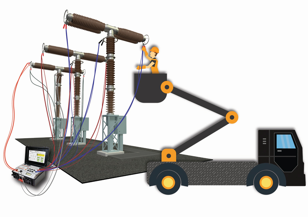
Figure 1 shows the connection of the circuit breaker analyzer and the timer. This type of lead connection includes cables for connection to all three phases for measuring operation timing as well as current-source leads to the specific phase where the static and dynamic resistance will be measured. The aggravating circumstance is that to measure the resistance of individual phases, the technician must switch the power source leads three times from one phase to another while performing the HVCB operation. The presence of numerous cables increases the likelihood of inducing high voltages, posing risks to test personnel and potentially leading to inaccurate test results if connections are improperly made.
To address these challenges, this new approach advocates for the modularization of measurement devices, which involves detaching the test equipment into a central unit (referred to as the master) and external modules (known as slaves) that contain high-capacity Li-Po batteries (Figure 2). By adopting this approach, the need for numerous long and heavy cables is minimized, simplifying the testing process and enhancing safety while optimizing time consumption.
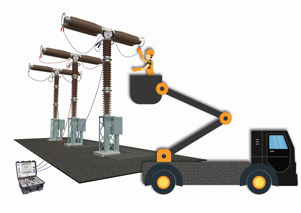
Figure 2 also shows the connection diagram of the circuit breaker analyzer and timer. This type of cable connection includes lightweight communication cables between the master device and slave test modules on each HVCB pole. In this configuration, weighty test leads connected from the test device to each pole are replaced by lightweight communication cables between master and slave modules and short, lightweight cables between modules and the circuit breaker main circuit. Additionally, all three tests are performed by the single test lead setup as one comprehensive test. With this configuration, it is also possible to perform each test individually.
Table 2 shows the required average preparation time for the test for a circuit breaker with two breaking points per phase, with the conventional and the new approach. As can be concluded with the new approach, the preparation time is 50% shorter.

METHOD VERIFICATION
Method verification has been performed on several high-voltage circuit breakers. This paper analyzes the results obtained on a Koncar 7E2, 420-kV circuit breaker with two breaks per phase. At the beginning of the testing, the circuit breaker was grounded on both sides, so simultaneous time and resistance measurements were made with the new method using external sources. Next, the ground was removed from one side, and the timing tests were repeated with the conventional method. Finally, the resistance measurement was performed with a standard built-in micro-ohmmeter using the conventional method to confirm the accuracy of the previously obtained results with external sources.
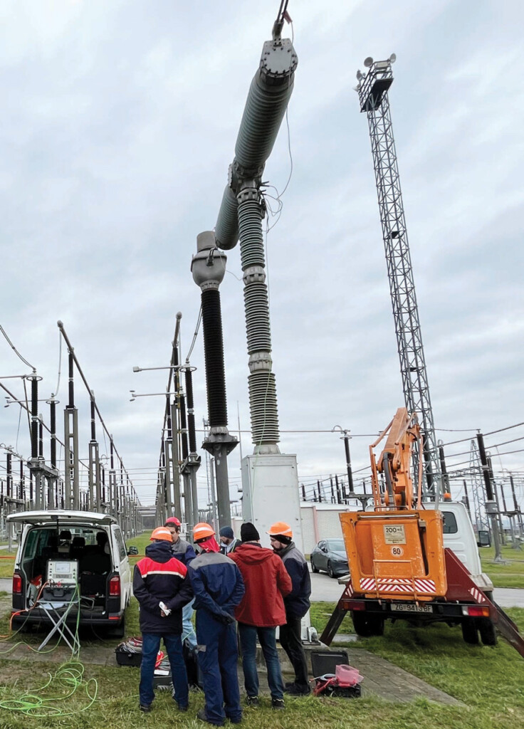
Figure 3 illustrates the setup for verifying the new method and shows the configuration of the Koncar 7E2 circuit breaker during the described testing phases.
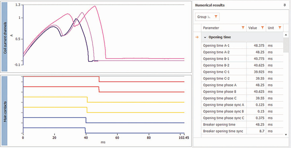
The graphical and numerical results of one opening test obtained with the conventional timing method are presented in Figure 4. It can be seen that there was a time discrepancy of about 8.7 ms between Pole A and Pole C, which exceeds the limits allowed according to IEC standards (3.33 ms for a 50 Hz network and 2.77 ms for a 60 Hz network). After closer analysis, it was suspected that the control circuit was related to this failure because the ends of the opening coil currents of the individual poles were displaced relative to each other by a similar amount of time. It was later found that the coil control valve that activates the hydraulic mechanism of Phase A was not properly adjusted.
If these results are compared to the results of simultaneous timing and DRM tests during the opening obtained with external modules (Figure 5), it can be concluded that these results are almost the same.
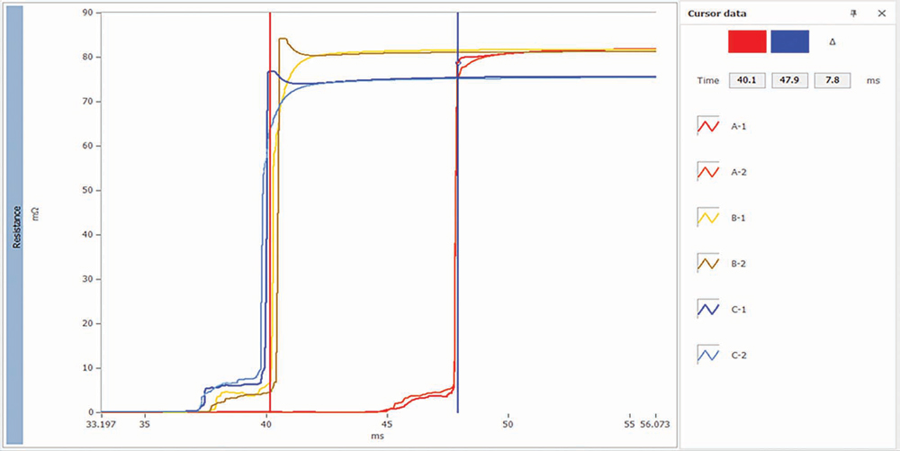
- Where DRM signals are shown, the blue cursor is positioned in the instant when Pole A opens (when resistance goes to infinity), showing 47.9 ms, which is very close to the result obtained with conventional timing (48.3 ms).
- The red cursor is positioned in the instant when Pole C opens, showing 40.1 ms, which is also very close to the result obtained with conventional timing (about 40.7 ms).
- The discrepancy between the A and C (7.8 ms) phases deviates slightly compared to the result obtained during the conventional test (8.7 ms). It should be noted that the differences between these results may also be due to the repeatability of the circuit breaker operations, i.e., defined allowed deviations of the circuit breaker operating parameters according to the OEM.
As can be seen in Figure 5, in addition to properly detecting opening time in a both-sides-grounded condition, this method provided DRM signals for all six breaking units simultaneously.
Graphical and numerical results obtained during the closing test with the conventional timing method are presented in Figure 6. The closing times of all breaking units are around 85–86 ms, and there is a time discrepancy of 1.5 ms between the slowest and fastest poles.
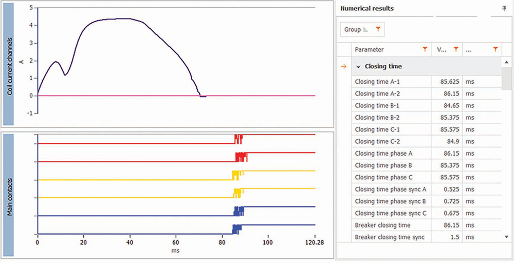
When compared to the results of the simultaneous timing and DRM closing test obtained with external modules (Figure 7), it can be concluded that these results match very well.
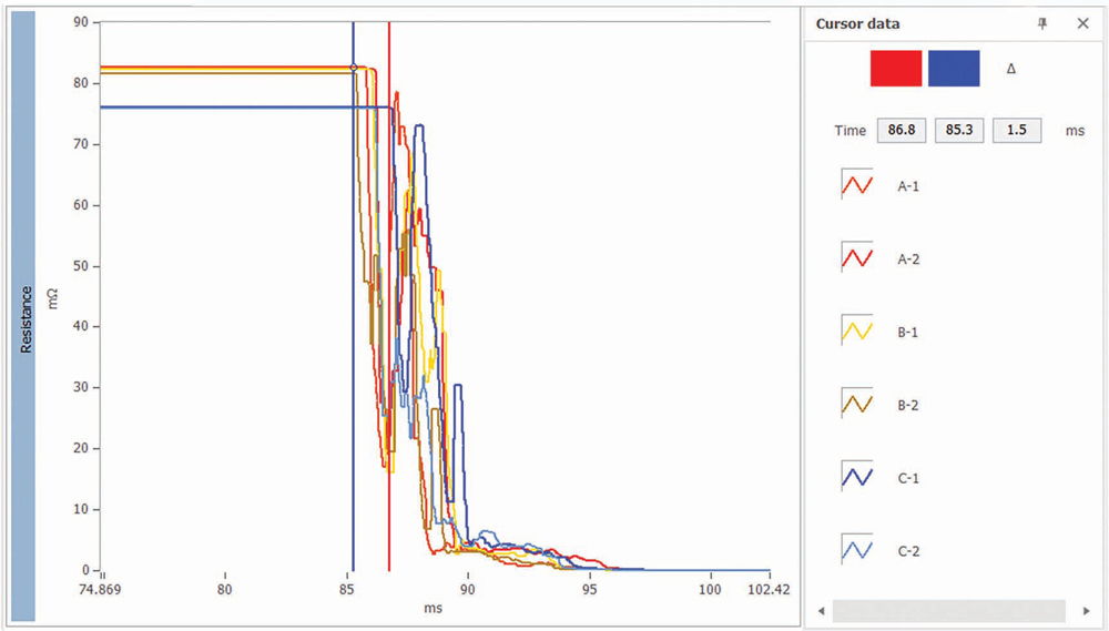
- Where DRM signals are shown, the blue cursor is positioned in the instant when the fastest breaking unit closes (85.3 ms) when resistance suddenly decreases.
- The red cursor is positioned in the instant when the slowest breaking unit closes (86.8 ms).
- The time discrepancy between the slowest and fastest breaking unit is 1.5 ms, which exactly matches the result obtained using the conventional timing method.
The analysis related to open and close time measurement is summarized in Table 3.

In addition to properly detecting closing time in a both-sides-grounded condition, this method provided DRM signals during closing operation for all six breaking units simultaneously.
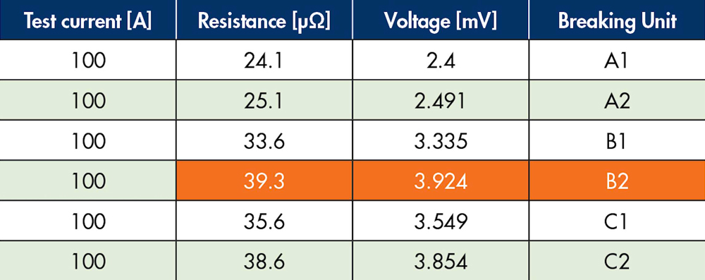
As a final proof, the contact resistance measurement results were considered. Results obtained for all six breaking units simultaneously using an external module are presented in Table 4.
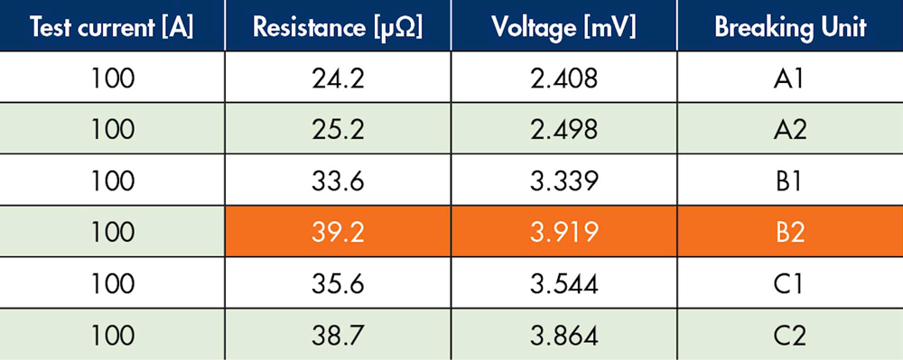
Table 5 presents the results of contact resistance measurements of each breaking unit obtained with the conventional method with one built-in current source. As can be seen, there are almost no deviations between the new test configuration and the conventional test configuration.
CONCLUSION
A new test method that requires test configuration with external modules has proven to be more efficient than conventional timing and contact resistance measurement methods. The test preparation time is significantly shortened, and the work engagement in test preparation is significantly reduced. This contributes to increasing the safety of test personnel and equipment, as well as reducing financial costs. With all these advantages, the measurement accuracy for all tests remained almost the same as for conventional methods.
REFERENCES
K. Obarčanin and S. Džuzdanović. “The Software Solution for the Presentation and Analysis of the High Voltage Circuit Breaker Timing Measurement Results,” Conference Proceeding Infoteh Jahorina, Vol. 15, Sarajevo, Bosnia and Herzegovina, March 2016.
K. Obarcanin, R. Ostojic, and S. Dzuzdanovic. “Parameters for Condition Assessment of the High-Voltage Circuit Breakers Arcing Contacts Using Dynamic Resistance Measurement,” 40th International Convention on Information and Communication Technology, Electronics and Microelectronics (MIPRO), Opatija, Croatia, 2017.
R. Ostojic, S. Vucicevic, B. Fazlic, and K. Obarcanin. “Application of Wireless Technologies for High-Voltage Circuit Breaker and Power Transformer Condition Assessment Test Instruments,” 19th International Symposium INFOTEH-JAHORINA, 18-20 March 2020, Sarajevo, 2020.
R. Ostojić and J. Levi. “Use of Micro ohm Meter as a Power Source for DRM Testing on Dead Tank Circuit Breakers,” 80th Annual International Doble Client Conference, 2013.
K. Obarcanin and R. Ostojic. “High-Voltage Circuit Breakers Arcing Contacts Operational Condition Indices Extracted from the Dynamic Resistance and Contact Motion Trajectory,” International Conference on Modeling, Simulation & Intelligent Computing (MoSICom), Dubai, United Arab Emirates, 2023.
C. L. Mariesa and S. Nirup. “Electric Power Measurements and Variables,” in Encyclopedia of Energy, Elsevier, 2004, pp. 245-254.
B. Rusek, G. Balzer, M. Holstein, and M.S. Claessens. “Timings of High-Voltage Circuit- Breaker,” Electric Power Systems Research, p. 78(12), 2008.
A. Šečić and R. Ostojić. “Combined Current and Voltage Controlled Source in Arcing Contacts Conditions Assessment,” NETA World, Winter2015.
F. Salamanaca, F. Borras, H. Eggert, and W. Steingaber. “Preventive Diagnosis on High-Voltage Circuit Breakers,” Proc. Cigre Symp., pp. 120-02, Berlin, Germany, 1993.

Lejla Dževlan is a Software Engineer at DV Power within the R&D team for high-voltage circuit breaker testing and condition assessment software solutions development. Dževlan’s work involves software aspects of testing methodologies, leveraging her expertise in software engineering to innovate in the field. Passionate about innovation, she contributes to advancing testing methodologies in the circuit breaker field and is actively involved in battery technology projects. She completed her master’s studies at the Faculty of Electrical Engineering, University of Sarajevo, Department of Automation and Electronics, and also studied at Mälardalen University in Sweden, specializing in intelligent systems.

Radenko Ostojić is a Test and Diagnosis Engineer at DV Power – Sweden in the field of circuit breaker testing and maintenance. He has been employed at DV Power since 2010 and works on improving circuit breaker testing equipment and developing new methods for circuit breaker testing. Ostojić’s area of special interest is testing circuit breakers in enhanced safety conditions, which implies testing circuit breakers with both terminals grounded. He earned his BSEE at the University of East Sarajevo.

Kerim Obarčanin is the Technical Director at DV Power – Sweden. He has almost two decades of experience in the measurement and instrumentation niche. His primary research focus is in the domain of data acquisition, conditioning, and algorithms for data processing. Along with his industry career, Obarčanin is in the final stage of his PhD studies at the Faculty of Electrical Engineering, University of Sarajevo, and is pursuing an academic career as an industry expert lecturer at two universities.

Dino Čikić is an Application Engineer with a primary focus on circuit breaker testing equipment. His role extends to offering technical assistance to DV Power clients across Europe, South Korea, and the CIS region, alongside conducting on-site circuit breaker testing. Čikić’s expertise lies particularly in micro-ohmmeters and circuit breaker analyzers, where he drives the development of advanced testing solutions. He earned a BS in electrical and electronics engineering from the University of Sarajevo.
