In an actual reported case, a severe storm blew down a large tree that struck a residence. A meter that should have been reporting 240 V reported a phase-phase voltage of 124 V. The falling tree had pulled down the service, which had then been re-attached by a service crew. A routine voltmeter check revealed 118 V between the left hot leg and neutral, but 241 V between the right hot leg and neutral. A proof test with a copper wire driven into the earth revealed 88 V between the neutral and the wire.
The socket enclosure was live! The service crew restoring the drop had mistakenly connected the socket’s neutral to an energized conductor. The transformer fuse had failed to blow. The socket was energized at 120 V, even though the socket had a driven ground rod. Poor grounding soil had rendered the rod inadequate to blow the transformer fuse and clear the fault.
Such an incident calls for a closer look at ground protection. When effective, grounding should protect persons from injury and property from damage. It should facilitate the operation of protective devices before damage occurs, and it should facilitate the operation of digital systems and the reliability of data.
A commonly heard aphorism states that current will follow the path of least resistance. This is of some interest as a generality, but is not strictly true. Current will divide according to the Law of Parallel Resistances. The danger here is the assumption that as long as the system is “grounded,” everyone is safe from shock and electrocution because fault currents will follow the “path of least resistance” into the earth via the grounding conductor and electrode (rod).
This is true as long as the grounding system doesn’t allow more than a few milliamps to pass through any alternative path, such as a human who has crossed a voltage gradient from an electric motor to a water pipe. And the tolerance isn’t much. A human body is shocked by 5 mA and injured by 10 mA. Therefore, the grounding system must be installed and periodically maintained at values within these parameters. Its mere existence is not enough.

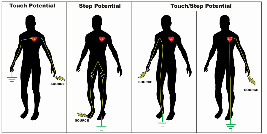
Figure 1: The human body can survive a considerable shock, but fault currents passing through the heart are most likely to cause a fatality.
In the United States, the utility may provide the customer with a solidly grounded system, an impedance grounded system, or an ungrounded system. Regardless of these alternatives, the customer will have a grounding electrode system and equipment grounding. Equipment grounding is a connection of non-current-carrying parts of the electrical system to ground. These can be motor frames, outlet boxes, conduits, raceways, cable armor, and the like. Connections must provide an effective ground-fault current path. In a solidly grounded system, the neutral points have been intentionally connected to earth ground as well.
The National Electrical Code (NEC) states that electrical equipment and wiring — including other conductive material likely to become energized — shall be installed in a manner that creates a low-impedance circuit that facilitates the operation of overcurrent devices or ground detectors for high-impedance grounded systems. This circuit must be capable of safely carrying the maximum ground-fault current likely to be imposed on it from any point in the wiring system where a ground fault to the electrical supply source may occur. The earth shall not be used as the sole equipment grounding conductor or effective ground-fault current path.
Therefore, all metering equipment (cabinets, conduits, sockets) must be bonded to system neutral for solidly grounded systems to prevent equipment from becoming energized in a line-to-ground fault. Relying on a ground rod alone may not provide enough current flow to clear a fault. If a meter control cable conduit is used for the bonding path, a bond must exist between the conduit and the enclosure. A bond wire can be installed in the conduit in lieu of using the conduit itself, as in the case of PVC conduit. The bond wire should be larger than the size of the meter control wires. If a metal conduit, the bond wire should be bonded to one end of the conduit, preferably the meter end.

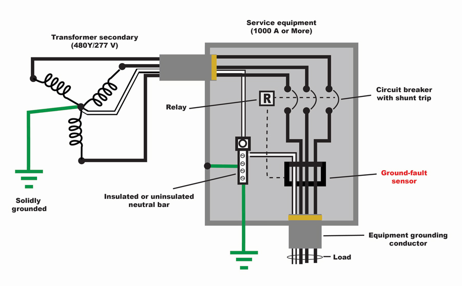
Figure 2a: Ground-Fault Sensor Installation Around All Circuit Conductors

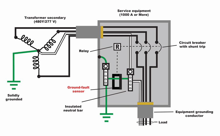
Figure 2b: Ground-Fault Sensor Installation Around Bonding Jumper Only
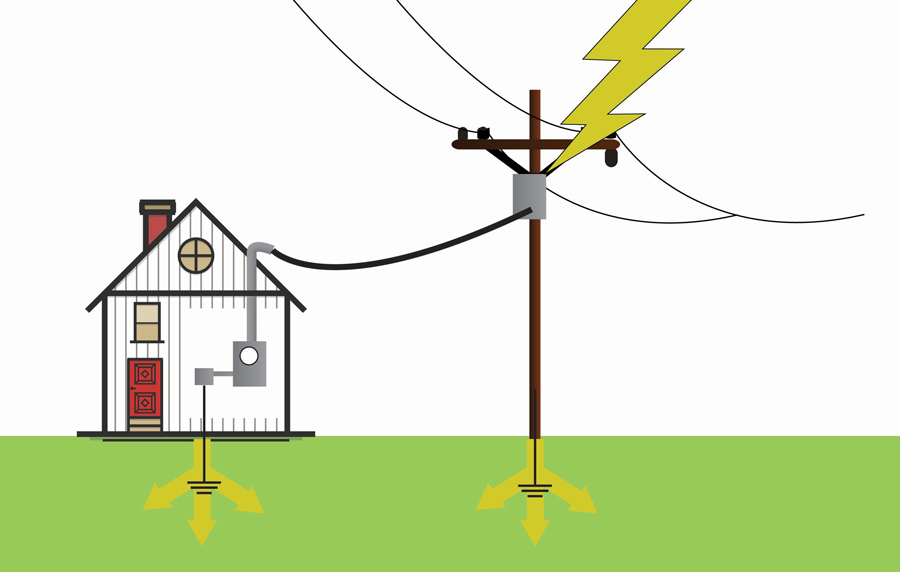
With the ground rod or other electrode (grid, mesh, etc.) being thus augmented by parallel connections, the question may be raised as to the usefulness of the rod itself. But the earth ground is invaluable in limiting the voltages due to lightning strokes, line surge, and other similar disturbances. The ground rod enables dissipation of lightning into the earth, where it will neutralize the buildup of charge in the clouds. System voltage to ground is thereby stabilized during normal operation, which is particularly useful in maintaining the operation of sensitive data systems within required parameters.

Figure 3: Ground electrodes are essential for lightning protection.
Separate grounding of the meter is not necessary if located close to the grounded service entrance or utility transformer. However, if located a distance away from both, it is suggested to ground the meter to neutralize any potential between the earth and the enclosure that is bonded to system neutral.
The primary purpose of the equipment grounding conductor is protection against shock and fire while providing a stable reference for electronic equipment. It is bonded to the neutral conductor and grounding electrode conductor at the service entrance, and there should only be one point of connection with the neutral conductor. The equipment grounding conductor does not carry current during normal operation — only in the event of a fault current. It is preferable to ground meter equipment by bonding to the system neutral inside the enclosure. The equipment grounding conductor may be required for grounding if the meter is located on the load side of ground-fault protection or on the load side of the service disconnect and a long way from it. Meter equipment should never be bonded to both the equipment grounding conductor and the neutral. This practice can create parallel paths for neutral current to flow on the equipment grounding conductor between equipment and service disconnect. It may flow across surfaces of sockets and enclosures. If the meter is on the load side of ground-fault protection, the enclosure can be grounded by the equipment grounding conductor.
Parallel paths for neutral current flow should not exist across surfaces of meter equipment or through grounding conductors inside enclosures. In order of significance, these unwanted currents can present a safety hazard, a fire hazard, and power quality problems. If a person gets in series with such an unexpected current, a fatality could result. Poor connections could result in heating from such a current and result in fire in severe cases. And such currents produce noise that affects the performance of sensitive electronic equipment.
Not all voltage systems are equal with respect to code requirements.
- The NEC recognizes a significant difference in safety between 120/208 V and 277/480 V systems with respect to arc faults and arc flashes. Article 230.95 requires ground-fault protection on 277/480 V systems rated 1,000 A and higher.
- IEEE adds some caution regarding clearance of enormous ground faults on higher energy systems. IEEE Std. 242–1986, Recommended Practice for Protection and Coordination of Industrial and Commercial Power Systems, 7.2.2 cites the high magnitude of ground-fault currents that can occur on solidly grounded 480 V systems. And IEEE Std. 141–1993, Recommended Practice for Electric Power Distribution for Industrial Plants, 7.2.4 states that solidly grounded systems are the most likely to escalate into phase-to-phase or three-phase arcing faults in 480 V and 600 V systems.
- NEC 230.95 calls for ground fault protection for solidly grounded wye services of more than 150 V to ground but not exceeding 1,000 V phase-to-phase for each service disconnect rated 1,000 A or more. These recommendations are based on awareness of arc fault danger on grounded 277/480 V systems. On larger services, the current required to sustain an arc can be less than the rating of the circuit breakers.
At the other extreme are ungrounded systems where there is no intentional connection between conductors and earth ground. These circuits have the advantage of continued operation after a ground fault on one phase. The purpose is to enable continued production in industrial facilities until a convenient time for shutdown and corrective maintenance. However, there are potential problems with allowing a ground fault to continue indefinitely. A voltage 1.732 times rated will appear on ungrounded phases. Transients of six to eight times normal voltage may appear from line to ground during normal switching, which can cause insulation failures on other points in the circuit, exacerbating the original problem. This can cause a second ground fault to appear on another phase, which in turn could develop a dangerous phase-phase fault.
High-impedance grounded systems have the neutral connected to ground through a resistance that limits ground-fault currents to very low values, typically under 10 A. By modifying the ungrounded system to mitigate some of the problems, the high-impedance ground also allows operation to continue so as to not limit production. Faults are easier to locate on this system than on ungrounded ones and can be removed. Transient over-voltages are eliminated. The disadvantages are similar to those on an ungrounded system. The unfaulted phases rise to line-to-line voltage, further stressing insulation. Additionally, a line-to-line fault can be created by a second line-to-ground on another phase. IEEE Std. 242–1986, 7.2.5 states that ungrounded systems offer no advantage over high-resistance grounded systems and are used less today than the latter.
CONCLUSION
Industrial production as well as office data management can be negatively impacted by poor or improper grounding. Personnel can be put in danger. It is advisable, therefore, to follow code and all relevant standards to keep systems operating at maximum efficiency and safety. Haphazard grounding can produce loss of revenue, fire, and even lethal accidents.
REFERENCES
Christian, Trent. “Grounding and Bonding Meter Sockets,” presented at Southeastern Meter School and Conference, Auburn University, August 2021.
 Jeffrey R. Jowett is a Senior Applications Engineer for Megger in Valley Forge, Pennsylvania, serving the manufacturing lines of Biddle, Megger, and Multi-Amp for electrical test and measurement instrumentation. He holds a BS in biology and chemistry from Ursinus College. He was employed for 22 years with James G. Biddle Co., which became Biddle Instruments and is now Megger.
