
This article presents a functional test procedure for a sudden pressure relay. The sudden pressure relay trips when it detects a sudden increase in gas pressure due to a fault internal to the transformer tank. Recommendations for mounting the relay and a procedure for post-analysis following field trips are also provided.
The sudden pressure relay (Figure 1) offers three main functions:
- Pressure sensing bellows
- Pressure equalizing orifice
- Microswitch
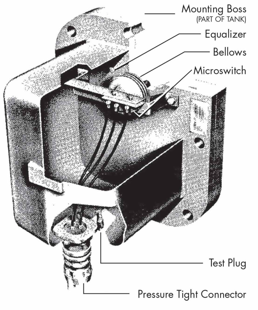
Figure 1: Sudden Pressure Relay
The bellows expands when an internal fault causes arcing, which operates the microswitch. The orifice is a plug with a very small hole that equalizes pressure inside the relay during slow changes due to transformer loading and ambient temperature changes.
Note: The sudden pressure relay can only be applied to transformers with a gas space above the windings inside the tank.
Sudden Pressure Relay Protection Characteristics
Figure 2A and Figure 2B illustrate the operating time to trip as a function of rate of pressure rise (psi/sec) and the time required to equalize the pressures between the transformer and sudden pressure relay respectively.
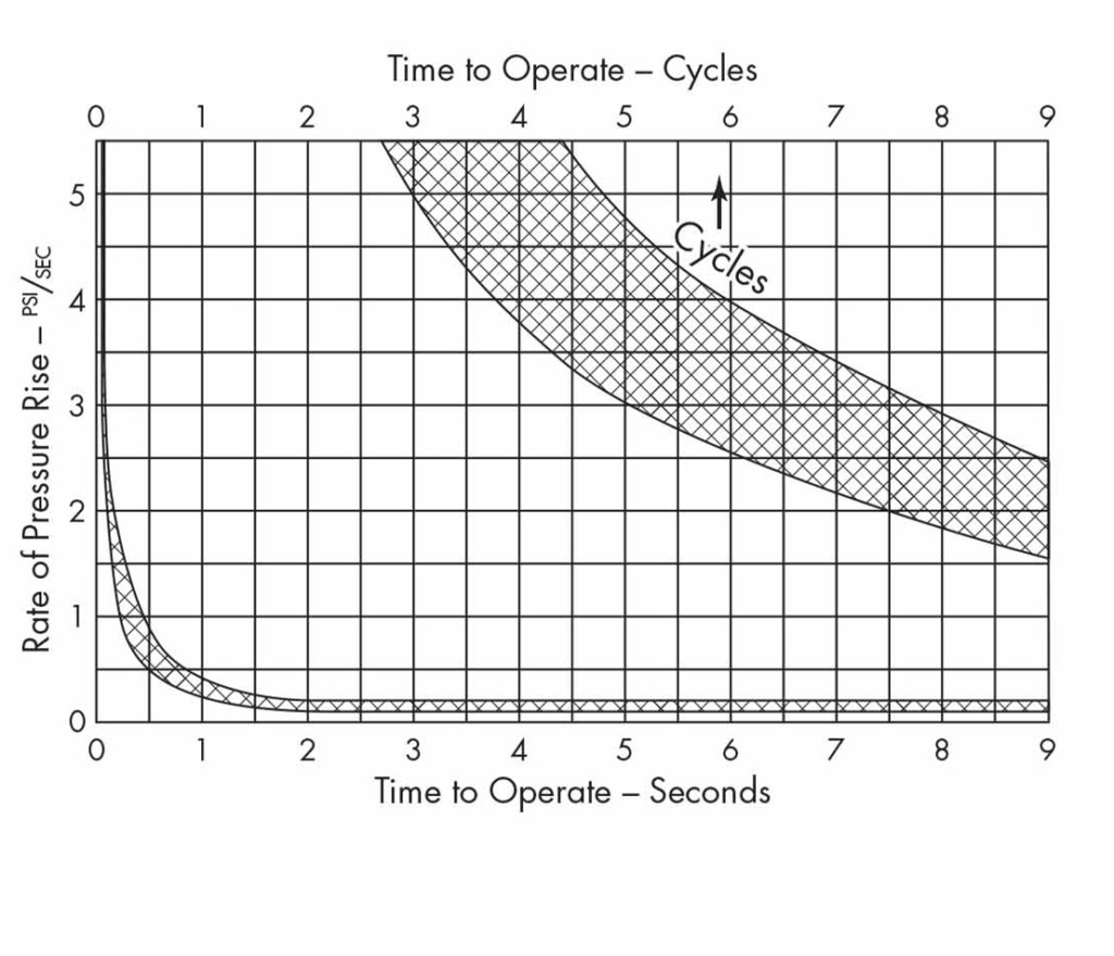
Figure 2A: Operating Characteristic
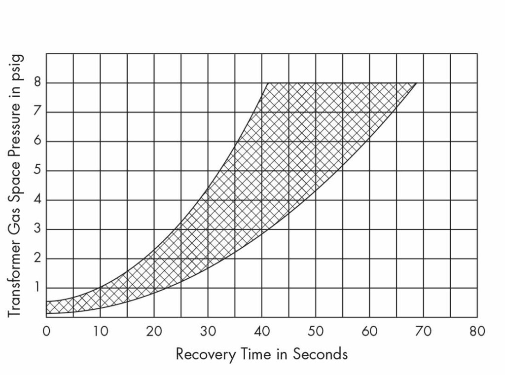
Figure 2B: Recovery Time
Sudden Pressure Relay Schematic
Typically, the relay includes a seal-in relay and a reset switch. The seal-in relay has alarm and trip contacts and is energized by the microswitch. It closes an alarm contact output and trips. It then seals itself closed until manually reset via the reset switch.
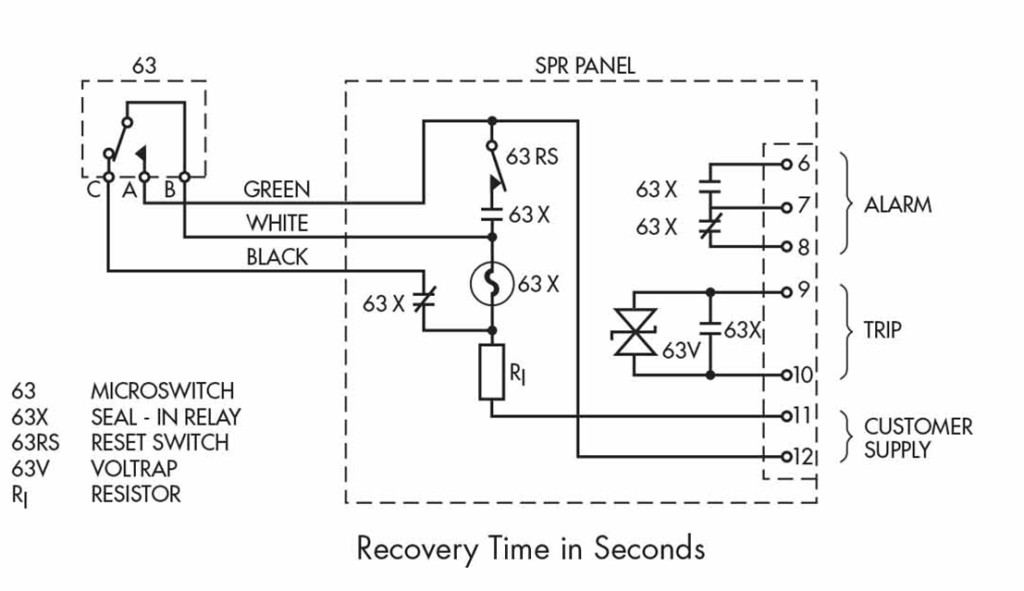
Figure 3: Schematic Diagram
Mounting Recommendations
Mount the relay above the maximum oil level in the gas space above the windings inside the tank. The relay mounting should be rigid and well-braced to prevent false operation due to any vibration, which can occur during close-in, high-magnitude through faults.
Figure 4 shows a sudden pressure relay mounted to a transformer tank.
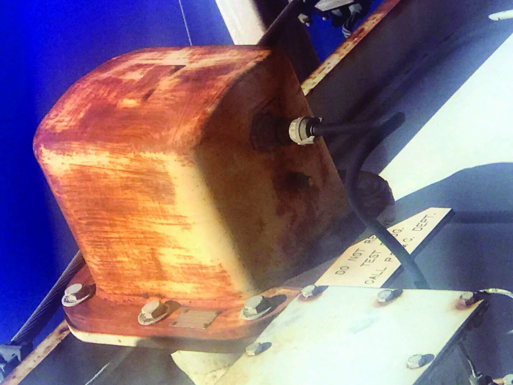
Figure 4: Sudden Pressure Relay Mounting
Functional Test Procedure
- Disconnect the sudden pressure relay supply voltage.
- Record the transformer operating pressure. The pressure must be greater than 3/4 psi for the following tests.
- Connect a circuit tester across terminals 1 and 2 on the terminal strip (B and C on Figure 3).
- Remove the test plug from the relay case. The relay microswitch will operate and the circuit tester will indicate a closed contact output.
- Close the test plug and record the time in seconds required for these same contacts to open.
- Using the recovery time recorded in #5 and the pressure recorded in #2 as coordinates on Figure 2B: Recovery Time, verify that the point is within the allowed operating area.
- Disconnect any external trip or alarm circuit.
- Check that the reset switch is closed.
- Reconnect the sudden pressure relay supply voltage.
- Connect the circuit tester across terminals 7 and 8.
- Remove the test plug. The relay will operate and the circuit tester will indicate an open circuit.
- Replace the test plug and allow sufficient time (see #5) for the sudden pressure relay to equalize.
- Operate the reset switch. The contact output across terminals 7 and 8 should fall closed. This check should be performed for each of the alarm and trip circuits.
- Reconnect the trip or alarm circuits following the correct operation of the relay.
Note: This test procedure is for a specific type of sudden pressure relay, so some steps may vary or not be necessary depending upon the actual type of relay that is being tested.
Testing After Field Operation
After a breaker trip resulting from operation of the sudden pressure relay, the transformer and the relay panel must be tested before it is re-energized to prevent possible damage to the coils and insulation.
Three checks are recommended prior to re-energizing the transformer:
- Functionally test the sudden pressure relay to determine if it is in proper operating condition.
- Conduct suitable tests and observations to verify that the transformer is undamaged and suitable for re-energization. Contact the transformer manufacturer if in doubt.
- Contact the transformer manufacturer for any additional instructions concerning maintenance and inspection procedures.
Reference
ABB. “Sudden Pressure Relay Technical Guide.” 1ZUA566ref-210–rev.2 September 8, 2009. Available at www.library.e.abb.com/public/7ecd37d3c79ef688c1256fa2007003cc/
1ZUA5663-210_r2_Sudden%20Pressure%
20Relay.pdf.
 Steve Turner is in charge of system protection for the fossil generation department at Arizona Public Service Company in Phoenix. After working with Beckwith Electric Company, Inc. for 10 years, Steve spent two years as a consultant in San Diego. His previous experience includes positions as an Application Engineer at GEC Alstom and in the international market for SEL focusing on transmission line protection applications. Steve also worked for Duke Energy (formerly Progress Energy), where he developed the first patent for double-ended fault location on overhead high-voltage transmission lines and was in charge of all maintenance standards in the transmission department for protective relaying. Steve has BSEE and MSEE degrees from Virginia Tech University. He has presented at numerous conferences including Georgia Tech Protective Relay Conference, Western Protective Relay Conference, ECNE, and Doble User Groups, as well as various international conferences. Steve is a senior member of IEEE and a member of the IEEE PSRC.