
Everyone has heard stale jokes about not reading instructions until it becomes a last resort. With many electrical test instruments, experience or general familiarity can at least get you started. But with ground testing, taking the new instrument out of the box and trying to figure out how to run the test will get you nowhere. There is nothing intuitive about a ground test. You can drive probes into the ground and get a reading of the resistance between them, but it means nothing. To secure vital information about the effectiveness of your grounding system, you must follow an established procedure that compensates for variables.
CLAMP-ON VS. TRADITIONAL TESTERS
Ground tests are performed using two distinct types of instrumentation: clamp-on testers and traditional models employing leads and probes. The latter are further divided into three- and four-terminal models. Before purchasing or acquiring a ground tester, these fundamental differences must be considered and evaluated.
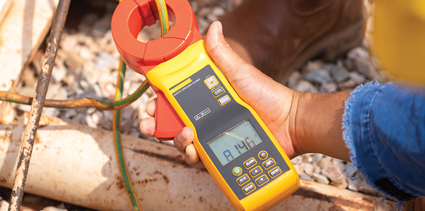
At a glance, the clamp-on ground tester resembles the familiar clamp-on multimeter, where the jaws are clamped around a current-carrying conductor and the current measurement is posted on the display. However, the jaws of a clamp-on ground tester have two windings: one to sense current and the other for voltage. With two measured parameters, the tester can calculate a third: resistance. The reading on the display is given in ohms. Beautifully simple, but what is it actually measuring? To complete the current loop back to the jaws and provide a measurement circuit, the tester must find its own path. This will usually be the nearby utility grounding system, such as pole grounds.
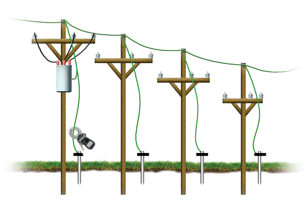
The success of the measurement depends on the existence of a return path close by and of negligible resistance so that it does not contribute a large error to the reading. A concentric neutral of buried power cable can also provide this element. When the clamp-on is energized, a test current is induced onto the clamped ground rod, travels through the electrode into the soil, and returns through the utility grounds and system neutral. This is bonded at the service entrance to the ground bus and therefore to the grounding conductor leading to the test item.
The procedure is simple but at risk of potential errors. An untrained operator can clamp the wrong part of the system and still get a reading that appears to be good. Traditional test methods require the stringing of leads and test probes, so the operator must have a general knowledge of the site and place the test probes accordingly. With a clamp-on tester, the operator has no such control and must accept the reading from the tester. In the extreme, there may be no return path at all. This would be the case with a newly installed ground that is not yet attached to the electrical system. The clamp-on has no path to complete a test circuit and is unable to perform critical commissioning tests that are often required before the electrical system is attached. This is an example of a test being defeated by an open circuit.
The other extreme is a short, and clamp-ons are at risk here too. The induced test current should travel through the soil and find a path back into the electrical system, usually relying upon the utility grounds of, say, a nearby pole line. But is the amount of soil traversed enough to truly represent the correct resistance to what is described as remote earth? This can be a matter of pure luck. With a traditional tester, the test results map the area and provide a clear indication of the maximum resistance that a fault current will encounter. A clamp-on measurement provides no such security and must simply be accepted.
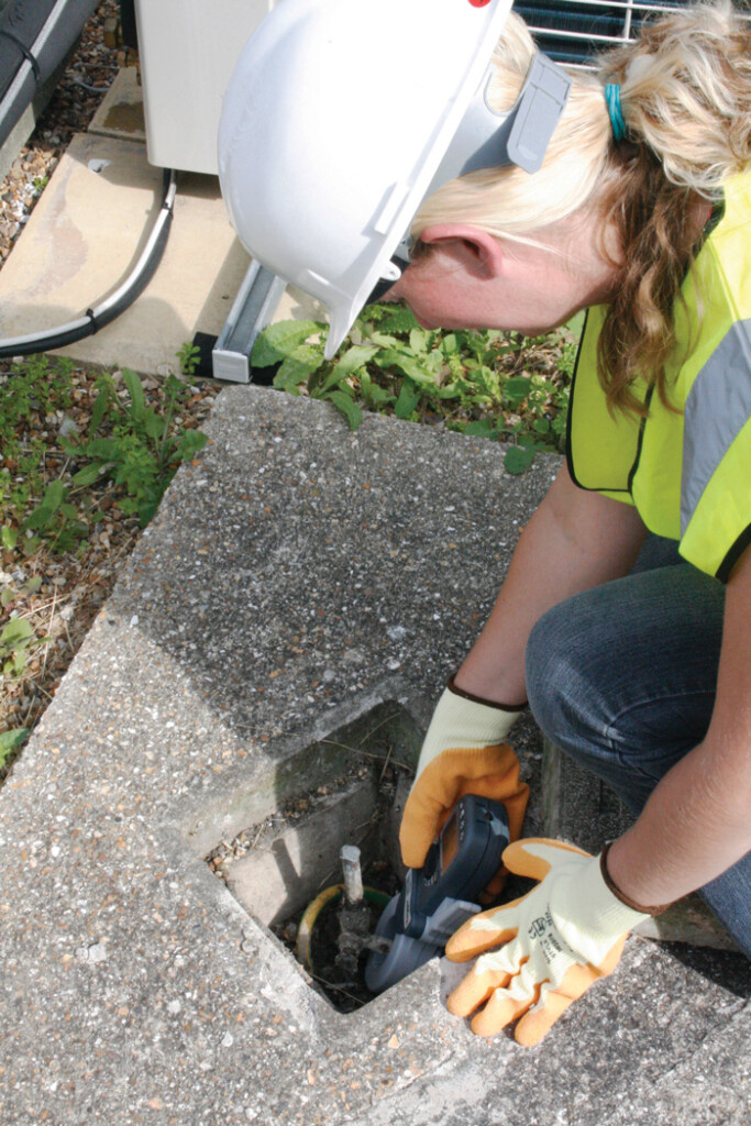
An additional consideration is measuring ground grids. There is no issue where a single ground rod exists, but grids often have multiple connections to the electrical system. In such cases, the clamp-on test current can merely circulate around the grid and provide a low reading that can be mistaken for a good ground measurement. With a clamp-on, the operator can be fooled into taking a continuity measurement for a ground measurement and recording it as such (Figure 2).
This problem doesn’t exist with traditional testing because the operator has placed the return probe outside of the sphere of influence of the grid. Uncommonly low readings from a grid should be regarded with suspicion and confirmed with additional scrutiny.
However, when viewed correctly, the clamp-on also performs a vital continuity test. The astute operator will spot corroded joints or loose connections. With a traditional tester, repositioning of leads and a second test are required, but with a clamp-on, a continuity test is simultaneous. The resistance of the return path…say, a line of pole grounds…is also included in the measurement and so should be minimized by judicious application. It cannot be completely eliminated, however, and clamp-on readings will always read a bit high. With a traditional tester, return resistance can be eliminated with a four-terminal or Kelvin bridge configuration.
How the test current goes to ground is critically different between a traditional tester and a clamp-on. With a traditional tester, current will divide according to the Law of Parallel Resistances through all paths to ground. When commissioning a new system, there is only one path. But if the electrode is connected to the electrical system, the utility ground is paralleled in and will be included in the measurement. This can pose a problem with lightning protection, which calls for the shortest, straightest path into the soil. A paralleled ground half a mile away is of no help. The on-site ground should be fully adequate, but to determine this, the utility ground must be lifted for the test, or the test current must be separately measured between the local and utility grounds. Some annoying arithmetic must also be applied to calculate the separate resistances.
The clamp-on eliminated this problem by its reverse configuration. By placing the utility grounds in series with the test ground, the test ground comprises nearly all of the measurement. The utility contributes only a negligible amount. Three-point traditional testers are configured with the local and utility grounds in parallel and the remote probe in series. The measurement is a combination of the resistances of both grounds, and the percentages require further exploration.
Advantages of Traditional Testers
As we’ve seen, the clamp-on presents a number of potential pitfalls in opposition to its major assets: simplicity and ease of operation. Traditional-style testers are at the opposite end of the spectrum: reliable, with provable results, but a lot of work. There are two standard configurations: three- and four-terminal testers.
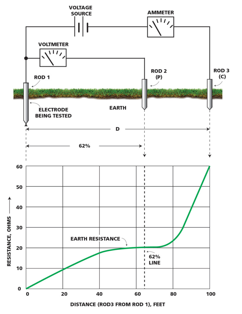
- Three-terminal models have a common that attaches to the grounding electrode under test. The other two are current and voltage. The current terminal attaches a long lead and probe, which are placed in the soil far enough away so that their electrical sphere of influence does not overlap with that of the ground under test (IUT). When the tester is energized, a test current is established through the soil from the remote probe to the IUT. This is of a distinct frequency that the measurement circuit can recognize apart from all noise traveling in the soil. The voltage terminal connects a second probe that the operator manipulates by taking a series of measurements along a line, preferably toward the current probe, although this is not always necessary in areas of heavy congestion. Each probe placement measures voltage drop and calculates the resistance to that point.
- The measurements are typically graphed, and modern testers do this automatically while displaying the graph as it is constructed. If the line continues to rise throughout (Figure 3A and B), the electrical zones of the test ground and current probe are overlapping, and the current probe must be moved farther away. With sufficient distance, the graph will level off.
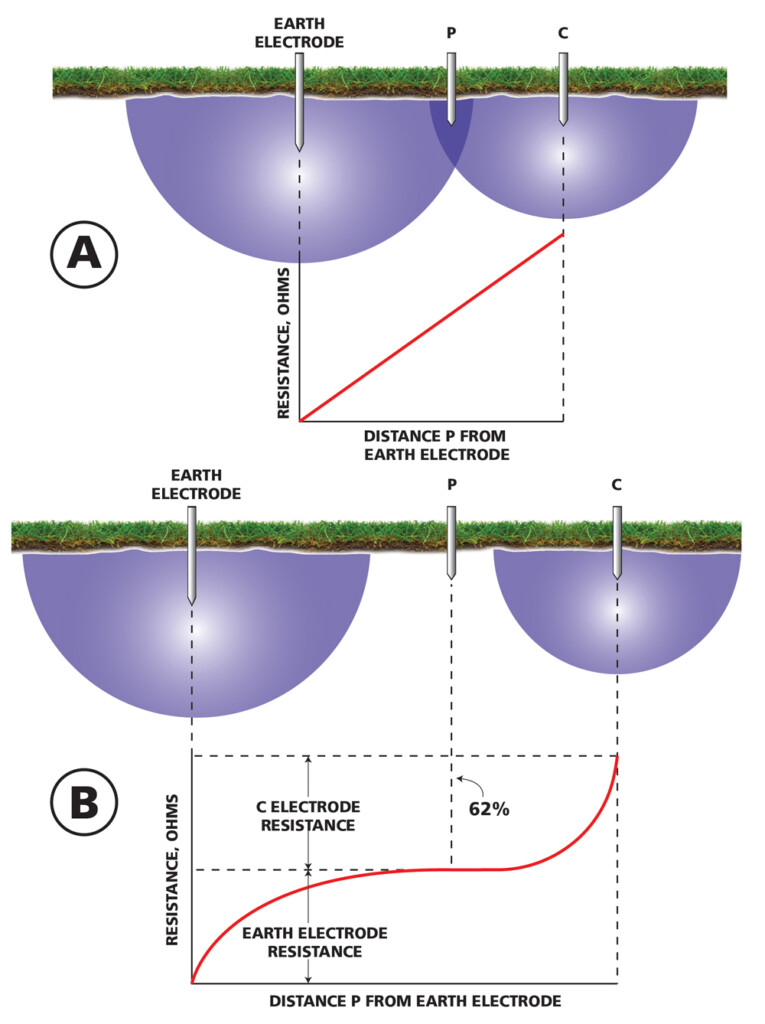
At some critical point, there is no additional resistance with added distance. Current going to ground radiates 360° around the grounding electrode, not in a straight line as in circuitry. Therefore, at some critical point, resistance maxes out, and there will be no additional resistance with distance. By plotting a series of measurements, this point and its associated resistance value can be read from a fall of potential graph (Figure 4). If it’s at, say, 2.5 Ω, you have a good ground. If it’s at 50, start adding more rods.
We can see here that a traditional ground tester provides much more information than a clamp-on, including assurance that the reading is correct. It does not have to be accepted on faith. But the trade-off is that it’s a lot of work. One additional qualification remains: that of three- and four-terminal testers. Both will provide a reading of resistance, but only a four-terminal model will measure resistivity. The terms are similar and easily confused, but resistivity is a measure of the electrical properties of the soil itself. Resistivity is vitally important in ground design and installation. Proper probe placement for this test requires four terminals.
CONCLUSION
Clamp-on, three-terminal, and four-terminal ground testers offer distinct features and advantages. If ground testing is a frequent activity, it’s a good idea to have at least two. Be sure to become familiar with the salient points of each type and be prepared to take maximum advantage of each.
REFERENCES
IEEE. IEEE Std. 81-2012, Guide for Measuring Earth Resistivity, Ground Impedance, and Earth Surface Potentials of a Grounding System. Available at https://ieeexplore.ieee.org/document/6392181. Note: The 2025 edition is currently classified as Active – Draft.

Jeffrey R. Jowett is a Senior Applications Engineer for Megger in Valley Forge, Pennsylvania, serving the manufacturing lines of Biddle, Megger, and Multi-Amp for electrical test and measurement instrumentation. He holds a BS in biology and chemistry from Ursinus College. Jowett was employed for 22 years with James G. Biddle Co., which became Biddle Instruments and is now Megger.