

Breaker failure protection provides backup protection in case the local circuit breaker fails to clear a system fault. If a breaker fails to trip, adjacent breakers must be tripped to isolate the fault from the sources feeding it.
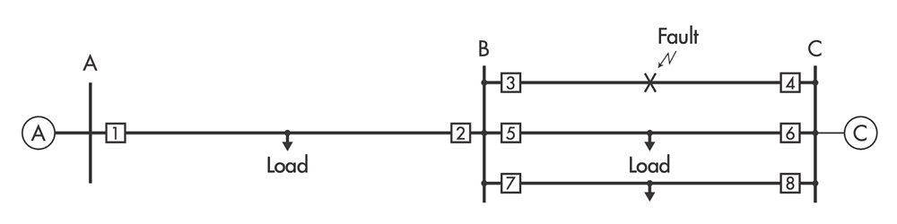
Figure 1 illustrates a fault on the transmission line served by Breaker 3 and Breaker 4. If Breaker 3 fails to open, Breaker 2, Breaker 5, and Breaker 7 must open to isolate Source A and Source C at Station B.
BREAKER FAILURE LOGIC
A time delay on the pickup timer starts timing when a trip signal is sent to the breaker. A dedicated 50-BF current-level detector measures the current flowing through the breaker. If current is still present when the timer expires, then a breaker failure trip signal closes an output contact, which trips the adjacent breakers. A typical time delay on pickup is 10 cycles. There must be enough time for the 50-BF current-level detector to drop out if the local breaker is slow to clear.
Figure 2 shows a timeline for the breaker failure scheme logic; normal operation is above the time axis. Normally, the main protection operates with no intentional time delay — for example, a Zone 1 distance protection trip. The local fault clearing time is equal to the local protective relay time plus the breaker interrupt time for a normal operation.
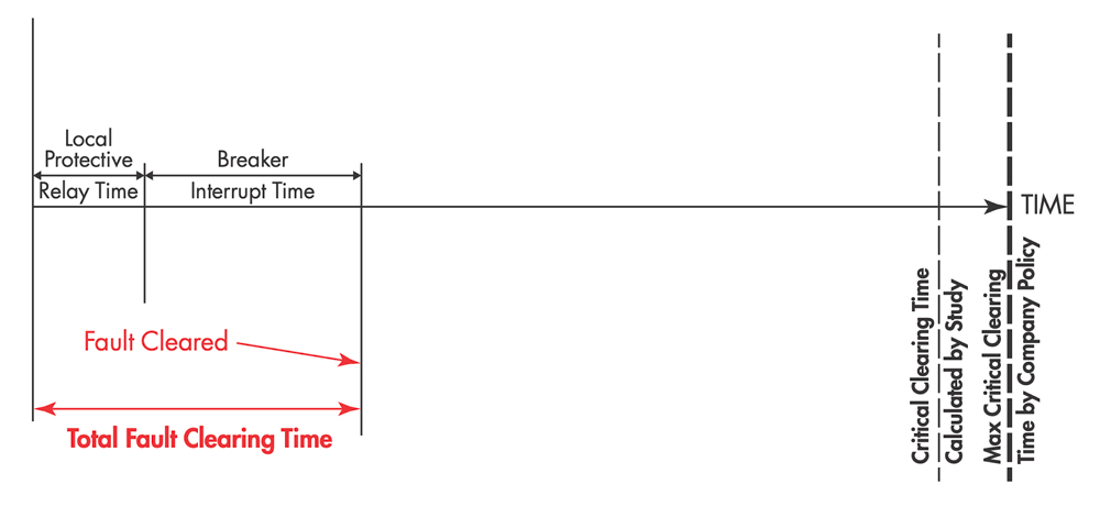
The total fault clearing time is the sum total of all time delays required to isolate the fault from the rest of the power system. The critical clearing time calculated by a study is the maximum amount of time that the fault can remain before the system loses synchronism and becomes unstable.
The fault must be cleared within this time delay to prevent a cascading system-wide failure. The critical clearing time calculated by the user is a safety margin applied to prevent cascading failures; the fault must be cleared within this time delay. The total fault clearing time must be less than the critical clearing time.
RETRIP LOGIC
A good practice is to have two trip coils for the breaker. A retrip is sent to the second trip coil prior to the breaker failure trip. This prevents a breaker failure trip if the first trip coil fails.
SUPERVISION BY BREAKER STATUS
There are situations during an abnormal system event where there is not enough available current to pick up a 50-BF current-level detector. Overexcitation for a generator is a good example: 24 volts per Hertz protection detects such a condition and operates on voltage only. The 52-A breaker status contact from the local breaker supervises the trip instead of the 50-BF current level detector.
CONCLUSION
This article illustrates the basic principles of breaker failure protection for transmission line breakers. It presents the timing diagram, which shows the sequence of operations, and gives fixed times that must be known. Retrip logic and supervision using breaker status are also presented.

Steve Turner is currently consulting. He was in charge of system protection for the Fossil Generation Department at Arizona Public Service Company in Phoenix, Arizona, for five years. Turner previously worked as a consultant for two years and held positions at Beckwith Electric Company, GEC Alstom, SEL, and Duke Energy, where he developed the first patent for double-ended fault location on overhead high-voltage transmission lines and was in charge of maintenance standards in the transmission department for protective relaying. He has BSEE and MSEE degrees from Virginia Tech University. Turner is an IEEE Senior Member and a member of the IEEE PSRC and has presented at numerous conferences.