Solar performance testing is crucial for verifying the efficiency and reliability of photovoltaic (PV) power systems. As solar installations become more prevalent, it’s essential to have testing plans in place to ensure systems are functioning optimally and meeting expected performance standards. This article explores the key components of a typical solar interconnection site, outlines an effective testing methodology, and discusses the critical principles and tools involved in comprehensive solar performance evaluation.
COMPONENTS OF A SOLAR INTERCONNECTION SITE
A typical solar interconnection site consists of several key components working together to convert solar energy into usable electricity:
Solar Panels (Modules)
- Photovoltaic cells convert sunlight into direct current (DC) electricity.
- Each module contains multiple cells connected in series, often with bypass diodes to mitigate the effects of partial shading.
Strings
- Multiple modules are connected in series to increase voltage to a level suitable for the inverter input.
- Strings often have in-line fuses that supplement protection at the combiner box.
Combiner Boxes
- These combine the output from multiple strings into a single output circuit.
- They usually contain fuses or circuit breakers for each string, providing overcurrent protection and a means of isolating individual strings for maintenance or troubleshooting.
- This is sometimes supplanted with outdoor field wiring harnesses as shown in Figure 1.

Load Break Disconnects (LBDs)
- LBDs allow manual disconnection of the solar array from the rest of the system
- These are crucial for maintenance and emergency shutdown, providing a visible means of isolation.
Inverters
- Inverters convert DC electricity from solar panels into alternating current (AC) for use in buildings or feeding into the power grid.
- These may be string inverters handling multiple module strings or microinverters attached to individual panels.
- Modern inverters often include advanced features such as maximum power point tracking (MPPT) and grid support functions.
SOLAR PERFORMANCE TESTING METHODOLOGY
An effective solar performance testing methodology involves a systematic approach to evaluate each component and the system. A testing sequence in this order allows for a progressive evaluation of the system, starting with basic safety and visual checks and moving toward more detailed performance analysis.
- Site survey and safety check. Assess the site for potential hazards and ensure all safety protocols are in place.
- Visual inspection of all components. Look for obvious signs of damage, wear, or improper installation.
- Insulation resistance testing. Verify the integrity of electrical insulation throughout the system.
- Open circuit voltage (VOC) measurement. Check voltage levels at various points in the system.
- Short circuit current (ISC) measurement.: Determine losses of modules and strings under load.
- I-V curve tracing. Obtain detailed performance characteristics of modules and strings.
- Inverter loading. Ensure inverters are operating at expected output levels.
- Infrared thermography. Identify potential hot spots or areas of concern in modules and other components.
Solar Performance Testing Toolkit
To conduct comprehensive solar performance testing, technicians should be equipped with the following tools:
- Multimeter rated for 1,500 VDC with a 25 A+ DC-rated ammeter clamp-on accessory essential for basic voltage and current measurements throughout the system.
- Insulation resistance tester (megohmmeter). Used to check the integrity of electrical insulation between current-carrying conductors and ground
- I-V curve tracer. A specialized instrument for capturing the current-voltage (loading) characteristics of PV modules and strings
- Infrared camera. For detecting temperature anomalies that may indicate performance issues or potential failure points
- Irradiance and ambient temperature meter. Crucial for accurately interpreting performance measurements in relation to environmental conditions
- Proper personal protective equipment (PPE). Insulated gloves (1500 VDC), safety glasses, and arc flash-rated clothing appropriate for the voltage and incident energy levels being worked with
Each of these tools plays a vital role in ensuring thorough and safe testing procedures.
Testing Principles
Effective solar performance testing relies on the principles of safety, accuracy, precision, and performance assessment.
Testing should be conducted at various locations throughout the installation, including individual modules, string connections, combiner boxes, inverter inputs and outputs, transformer connections, and the grid interconnection point. This comprehensive approach ensures that all system components are thoroughly evaluated.
Standards and Requirements
Solar performance testing should adhere to industry standards and local regulations, including:
- IEC 62446, Grid Connected Photovoltaic Systems. Minimum requirements for system documentation, commissioning tests, and inspection
- IEC 61215, Terrestrial photovoltaic (PV) modules. Design qualification and type approval
- Local electrical codes and utility requirements
Familiarity with these standards ensures that testing procedures are in line with industry best practices and regulatory requirements.
Insulation Testing
Insulation testing checks the electrical isolation between current-carrying components and ground. This is crucial for:
- Safety assurance
- Preventing ground faults
- Identifying potential points of failure
The insulation resistance test should be performed with a megohmmeter, applying the appropriate test voltage based on system ratings. Typical test voltages range from 250 V to 1,000 V DC, depending on the system’s operating voltage. Results should be compared against minimum acceptable values as specified in relevant standards or manufacturer guidelines.
Open Circuit Voltage (VOC) Testing
VOC testing is one of the most critical tests to perform before connecting modules into strings and strings into combiner boxes. It verifies that the polarity and voltage for each module, string, and combiner match the manufacturer’s specifications. This ensures that everything is connected correctly and operating within design parameters.
VOC testing should be conducted at the following points:
- Individual modules. To verify manufacturer specifications and identify any outliers
- Strings. To ensure modules were connected in series with the correct polarity
- Combiner box inputs and outputs. To confirm each string’s polarity and voltage level before combining it with other strings. Improper string polarity and voltage can cause severe and permanent damage to the equipment being installed.
- Load-break disconnect terminals. To verify the expected voltage from the combiner box
- Inverter DC inputs. To ensure voltage from the load break disconnect is as expected
Before connecting each string to the combiner box, measure the voltage difference (V-diff) between each string wire of the same color to ensure they measure zero voltage, confirming the same polarity. This simple check can prevent potentially damaging reverse polarity connections.
I-V Curve Tracing
I-V curve tracing is a powerful diagnostic tool that provides detailed information about PV source performance. The methodology involves placing a variable load across a PV source (module, string, or array) and measuring current and voltage at multiple points as the load is varied from open circuit to short circuit. This creates a curve that characterizes the PV source’s performance under the given environmental conditions.
I-V curve traces should be performed at the following points:
- Individual modules. To identify any underperforming or damaged modules
- Strings. To verify proper string performance and detect any mismatch issues
- Array level. To assess overall system performance (where equipment allows)

When interpreting I-V curve results (Figure 2 and Figure 3), technicians should analyze:
- Maximum power point (Pmax). The point on the curve where the product of current and voltage is highest
- Fill factor. A measure of the squareness of the I-V curve indicating overall cell quality
- Series and shunt resistance issues. Identified by deviations in the curve shape
- Potential shading, soiling, or mismatch problems. Often visible as steps or notches in the curve

Comparison of measured curves to predicted (calculated) curves, based on measured irradiance, temperature, and module specifications, can quickly identify performance issues.
Common deviations from the raw data include:
- Low short-circuit current (ISC). Affects the overall height of the I V Curve and may be caused by uniform soiling, irradiance measurement error, or module degradation.
- Low open-circuit voltage (VOC). Affects the width of the I-V curve and couldindicate shorted bypass diodes, missing modules, or potential induced degradation (PID).
- Rounder knee. Often a sign of normal aging that should be monitored over time, a rounder knee can indicate decreased fill factor and overall efficiency.
- Low voltage ratio (VMP/VOC). Characterized by a steeper slope in the vertical leg of the I-V curve, may indicate excessive series resistance due to connection issues or module degradation
- Low current ratio (IMP/ISC). Characterized by a steeper slope in the horizontal leg of the I-V curve, could be caused by reduced shunt resistance or localized shading/soiling.
Technicians should use a systematic approach to identify and diagnose these deviations effectively. This helps eliminate environmental factors and measurement errors before concluding that there’s a hardware issue.
Bifacial Panels
It is important to recognize that solar panels with bifacial gains may show higher than expected values. Bifacial panels are built such that both sides can receive light and produce energy. During the winter, for example, light would hit the snow underneath and bounce back and hit the bottom side of the panel. Most IV curve models only account for one side being lit at a time. However, there are ways around this such as creating a temporary backing for the panel or array so it cannot receive light on the backside while being tested.
Best Practices for IV Curve Trace Measurements
To ensure accurate and reliable performance measurements:
- Conduct tests under stable weather conditions with irradiance above 700 W/m² when possible.
- Use proper irradiance sensors with spectral responses matching the PV modules being tested.
- Take care when measuring cell temperature, using light-gauge thermocouples for best results.
- Position temperature sensors in thermally representative locations on the modules.
- Be aware of potential sources of measurement error, such as rapid changes in irradiance or temperature.
- Calibrate all measurement equipment regularly to ensure accuracy.
- Document all test conditions thoroughly, including weather, time of day, and any site-specific factors that may influence results.
INFRARED THERMOGRAPHY
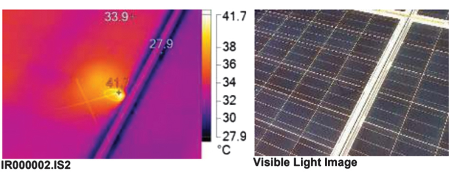
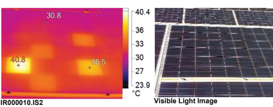
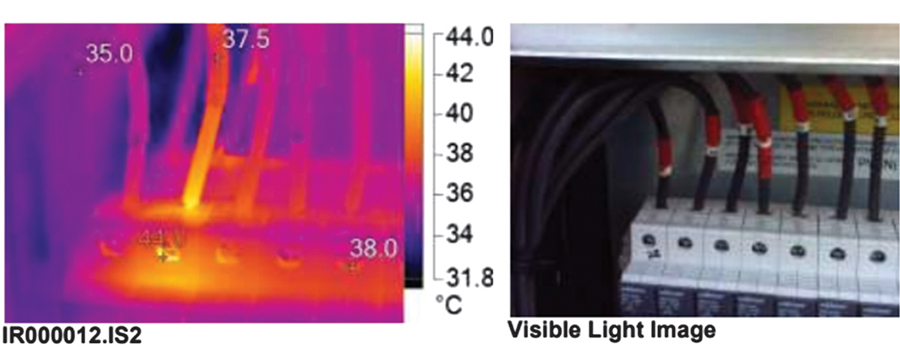
Infrared imaging is a valuable tool for identifying potential issues (Figure 4 and Figure 5) in solar installations. It can help detect these characteristic faults:
- Hot spots in modules. May indicate cell damage, internal connections, or bypass diode issues.
- Connection issues. Overheating at connections can signal high resistance points.
- Potential equipment failures. May signal abnormal heating patterns in inverters or other components.
- Uneven heating in components. May indicate uneven current distribution or other issues.


Infrared Scan Locations
Infrared scans should be conducted at the following points:
- DC panels/modules. To identify cell or bypass diode issues
- DC string connections/wires. To check for high-resistance connections
- DC combiner boxes. To inspect fuses, terminals, and busbars for abnormal heating
- DC load break disconnects. To examine terminals and switch mechanisms
- AC/DC inverters. To look for unusual heat patterns in inverter components
- AC circuit breakers. To check for overheating in breakers and their connections
- AC cables. To scan for any signs of overheating or insulation issues
- Transformers. To examine transformer surfaces and connections for abnormal temperature patterns
When performing infrared thermography, it’s important to consider factors such as emissivity, reflections, and thermal diffusion to ensure accurate results. Infrared scans are most effective when conducted during periods of high irradiance to maximize temperature differentials.
IRRADIANCE TESTING
Irradiance, the power per unit area received from the sun, is a critical factor in solar performance testing. It affects:
- Power output of solar panels
- Efficiency calculations
- Performance ratio determinations
Accurate irradiance measurements are essential for meaningful performance evaluations. Irradiance sensors should be calibrated regularly and positioned in the same plane as the solar array. When interpreting test results, it’s crucial to consider the relationship between irradiance and system output.
Optimal testing conditions include clear, sunny days with stable irradiance levels (preferably above 700 W/m²), minimal shading, and moderate temperatures to avoid temperature-related performance variations. However, tests may need to be conducted under less-than-ideal conditions in real-world scenarios, making it even more important to accurately record environmental conditions during testing.
WARRANTY CLAIMS AND REMEDIES
Test equipment can be valuable in the warranty claim process, helping to identify and document performance issues caused by isolated failures, systemic degradation, or poor installation practices. While manufacturers may require additional testing, the field measurements detailed in this text can be a helpful start to a warranty claim.
When pursuing a warranty claim:
- Document all testing procedures and results thoroughly.
- Compare measured performance to the manufacturer’s guaranteed values, accounting for age and environmental factors.
- Provide clear evidence of any defects or underperformance, including I-V curves, infrared images, and visual documentation.
- Follow manufacturer-specific procedures for submitting warranty claims.
CONCLUSION
Professionals in the electrical testing field should commit to ongoing education and training to stay on top of the latest developments. This commitment to a long career of learning will not only improve the quality of individual installations but will also contribute to the overall advancement of the solar energy industry.
Comprehensive solar performance testing is essential for ensuring the safety, efficiency, and longevity of PV power systems. By following a systematic approach and utilizing the right tools and techniques, technicians can verify that solar installations are operating at peak performance and identify any issues before they become significant problems.
Regular testing and maintenance based on these principles will help maximize the return on investment for solar energy projects and contribute to the reliable generation of clean, renewable energy. As solar technology continues to evolve, staying current with testing methodologies and equipment will be crucial for commissioning systems and maintaining system performance.
By combining visual inspections, electrical measurements, performance assessments, and thermal imaging, solar professionals can gain a comprehensive understanding of system health and performance. This holistic approach to solar performance testing ensures that PV installations continue to operate efficiently and reliably, supporting the growth of sustainable energy solutions worldwide.

Ben Clark, PE, is Manager, Capital Programs at LUMA Energy. He specializes in the management, design, testing, and instruction of utility and industrial power systems. Clark began his career as a third-generation electrician and now holds NETA Level IV Certification and is a licensed Professional Engineer. He earned a BS in electrical engineering from the University of Maine and an MS in electrical engineering from Worcester Polytechnic Institute.
