

Partial discharge is a poorly understood phenomenon, made harder to understand because many different units are used to measure it. Making matters worse, sometimes you have to calibrate a test setup, and other times you don’t. This article explains the various units, when and how they are used, and why we calibrate (sometimes).
MEASURING PARTIAL DISCHARGE
Partial discharge is a pulsed transfer of electrons from one point to another. A voltage difference builds up across a void as a number of electrons on one side. The discharge is the act of those electrons going to the other side of the void. The electrons then must go somewhere, and that action is a current pulse.
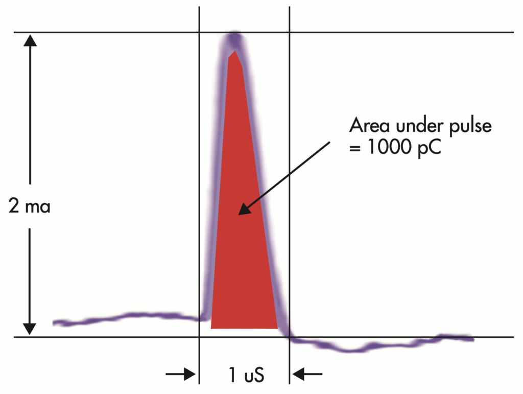
The scale of the discharge is the number of electrons, measured in Coulombs. One coulomb is 6,241,509,750,000,000,000 electrons, which explains why we don’t work in coulombs. One picocoulomb (pC) equals 6,241,509 electrons. Discharge of electrons can cause a current, but only for as long and as large as those electrons can produce. One coulomb can produce 1 amp of current for 1 second (1 amp-second). Similarly, a picocoulomb can produce 1 picoamp-second. This could be 1 amp for 1 picosecond, or 1 picoamp for 1 second, or anything in between. Typically, you see pulses in the range of microamps for microseconds.
If you can see the shape of the current pulse (Figure 1), the area under the pulse shape is the charge in pC. This is what measuring devices based on high-speed, high-quality high-frequency current transformer (HFCT)/radio frequency current transducer (RFCT) do. By measuring and calculating the area under the current/time pulse shape, you directly measure the number of electrons and therefore can read out the direct value in pC. If your HFCT and measuring circuit are known to be accurate, no further calibration is needed.
IEC 60270:2000, High-Voltage Test Techniques – Partial Discharge Measurements, the standard for offline PD testing, brings in the concept of apparent charge. When this charge is applied to the measuring circuit, it gives the same readings as the same charge in the test subject, which is not measured directly. Because the relationship between the reading and the actual PD is variable and dependent on the item under test, we must use a calibrator to establish a known relationship and get usable readings. The calibrator injects a known charge, and the resultant reading is used to scale the measurement values.
WHAT ARE DB, DBMW, DBMV, AND DBµV? AND HOW MANY DB IN A PICOCOLOUMB?
Many manufacturers and even ANSI/NETA MTS, Maintenance Testing Specifications For Electrical Power Equipment, use various units. Ultrasonic and transient earth voltage (TEV) readings are often given in dB, dBmV, or dBµV. We get asked all the time what reading corresponds to what pC discharge. These completely different quantities are measured with different modalities, and they can only be loosely related to pC.
Decibels or dB is a unique scale developed by engineers to confuse everyone else. Seriously, it’s a great tool for simplifying relative measurements when there can be great differences. For example, the power output of the sun is around 300 dBmW (5×1029 mW), and the power output of a laptop Wi-Fi signal is 15 dBmW (32 mW). Therefore, the difference is 275 dB. You can see how it makes it easy to work with big numbers and ratios.
Rules to Remember
a. A partial discharge dB number can be negative. dB is a power ratio, not an absolute measurement. When we say “10 dB,” we mean 10 dB higher than something else. When we say “-10 dB,” we mean 10 dB less than something else, not a negative level.
b. A partial discharge dB number has a fixed reference. By adding a fixed reference, we can turn this ratio into an absolute measurement. For example, dBmW is dB compared to a 1 mW reference. So, 0 dB = 1 mW. A negative dB would be below 1 mW (-10 dBmW = 0.1 mW), and a positive level is above 1 mW (+10 dBmW = 10 mW).
c. The dB number is logarithmic. So the equation of dB equals 10 log10 (x/ref), where x is the signal being measured and ref is the fixed reference. So 10 mW = 10 log10 (10/1) = 10. Table 1 shows some common power-level conversions.
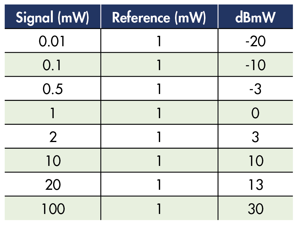
UHF PD Measurements (dBmW)
UHF measurements are made by a radio receiver picking up energy that is hitting an antenna. Like most radio receivers, it measures power. Therefore, UHF receivers tend to display in dBmW and use a scale like that described above.
TEV PD Measurements (dBmV)
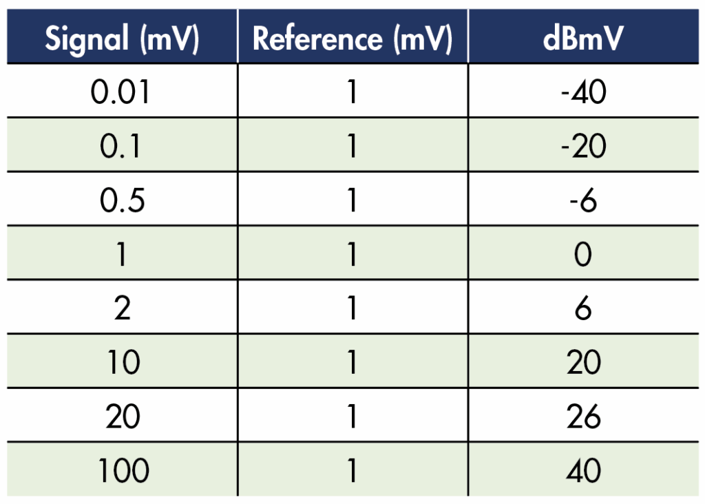
Transient earth voltage TEV) is a measurement of voltage on the outside of a grounded metal enclosure containing high-voltage assets. The partial discharge sends electrons to the surface of the enclosure, where they go across the impedance of the ground system, thereby creating a voltage. The TEV measuring device picks up that voltage through capacitive coupling. The measurement is an actual voltage.
As the high-frequency impedance of the ground system and the percentage of current flowing through that panel are unknown, and the coupling between the discharge source and that panel is unknown, it is impossible to consistently relate a discharge level to a TEV level. Therefore, the instrument displays the measured voltage on a logarithmic dB scale as described above.
Actually, dB is a power ratio, but TEV is measured in voltage. When using the scale to indicate volts, the dBmV numbers are doubled from the previous formula to dBmV = 20 log10(x/1mV). This is because for a given impedance, the power is proportional to the voltage squared. Table 2 shows conversions from the voltage to the dBmV scale.
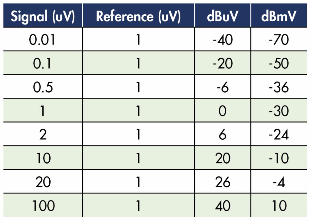
Ultrasonic PD Measurements (dBuV)
Ultrasonic measuring equipment takes the sound pressure level and converts it to a voltage via an ultrasonic sensor. In a similar fashion to TEV measurements, the voltage is presented in a logarithmic scale, but now relative to 1 uV. The formula is dBuV = 20 log10 (x/1uV). For reference, converting from dBuV to dBmV (Table 3) is as simple as subtracting 30.
Ultrasonic levels are highly variable based on the location of the discharge, the location and direction of the sensor, as well as any blockage, reflections, or absorptions of the signal. The presence of clear ultrasonic discharge patterns, regardless of the exact level, is a cause for concern.
HOW DO I KEEP ALL THESE LEVELS STRAIGHT?
Remember these scales:
- Offline PD = pC (inferred after calibration)
- Online HFCT-based testing = pC directly measured
- Online TEV-based testing = dBmV
- Online ultrasonic based testing = dBuV
Several manufacturers and even the NETA MTS 2023 standard use the convention to just say “dB” as the units, even though that is technically incorrect.
The severity of PD related to all these readings is best found in the NETA MTS standard and with manufacturers who have thousands of test results showing the relationship between the dBxx values and real-world PD.
If you are still confused, be glad you aren’t in the voice telecom world, where it gets even worse with terms like dBrnc0 (power level in dB above a reference noise source with a c-message weighting measured at zero transmission level point).

REFERENCES
- IEC 60270:2000, High-Voltage Test Techniques – Partial Discharge Measurements. Available athttps://webstore.iec.ch/en/publication/1247.
- ANSI/NETA MTS–2023, Maintenance Testing Specifications For Electrical Power Equipment. Available athttps://www.netaworld.org/standards/ansi-neta-mts.

William G. Higinbotham served as President of EA Technology LLC, a company he founded in 2013, until December 2024. In this capacity, he managed the overall operations of the organization, which represents EA Technology’s activities across North and South America. His responsibilities included leading sales, service, support, and training initiatives for partial discharge instruments and condition-based asset management systems. Higinbotham now serves as Chief Engineer, overseeing technical support for customers within his assigned territory. Before his tenure at EA Technology, Higinbotham served as Vice President of the Research and Development Engineering group at RFL Electronics Inc. from 1988 to 1994. His work there encompassed corporate management, new product development, manufacturing engineering, and technical support. An active contributor to the electric power systems field, Higinbotham is a Senior Member of IEEE and has co-authored several IEEE standards related to power system protection and communications. He is a published author, contributing to several industry journals, including NETA World, and technical papers, and holds a patent in this field. Higinbotham earned a BSEE from Rutgers University’s School of Engineering in 1984. He began his professional career in biomedical engineering, where he worked for four years before joining RFL.